
Method for operating remote electrical distribution equipment with transitional light-emitive member disposed intermediate an elongate member and a tool

a technology of transitional light-emitting member and elongate member, which is applied in the direction of couplings, contact mechanisms, hot sticks switches, etc., can solve the problems of complex installation of hook sticks, system faults, and difficult operation of hook sticks

Inactive Publication Date: 2003-11-04
TAYLOR MADDOX TECHN
View PDF15 Cites 15 Cited by
  • Summary
  • Abstract
  • Description
  • Claims
  • Application Information

AI Technical Summary

Problems solved by technology

Rings operated by hook sticks are difficult and cumbersome to operate.
The difficulty of inserting the hook stick into the ring is further complicated by the conditions in which electrical system faults generally occur.
High winds and lightening are leading causes of system faults.
Therefore, the need to operate a cut-out switch often occurs during poor weather and at night.
Placing the hook stick into the relatively small ring near an upper portion of a utility pole is even more an arduous a task in wet, windy, and dark conditions.
This is a difficult task, even for such electrical distribution devices known as cut-out switches that use rings or hooks for the operational catches that are engaged by the extendosticks.
These factors may cause numerous failed attempts to place the hook stick into the ring, and work becomes time consuming.
Failed attempts to inset a hook stick into a pole ring increases the exposure of the lineman to weather conditions or electrical hazards.

Method used


Image

  • Method for operating remote electrical distribution equipment with transitional light-emitive member disposed intermediate an elongate member and a tool
  • Method for operating remote electrical distribution equipment with transitional light-emitive member disposed intermediate an elongate member and a tool

Examples


Embodiment Construction

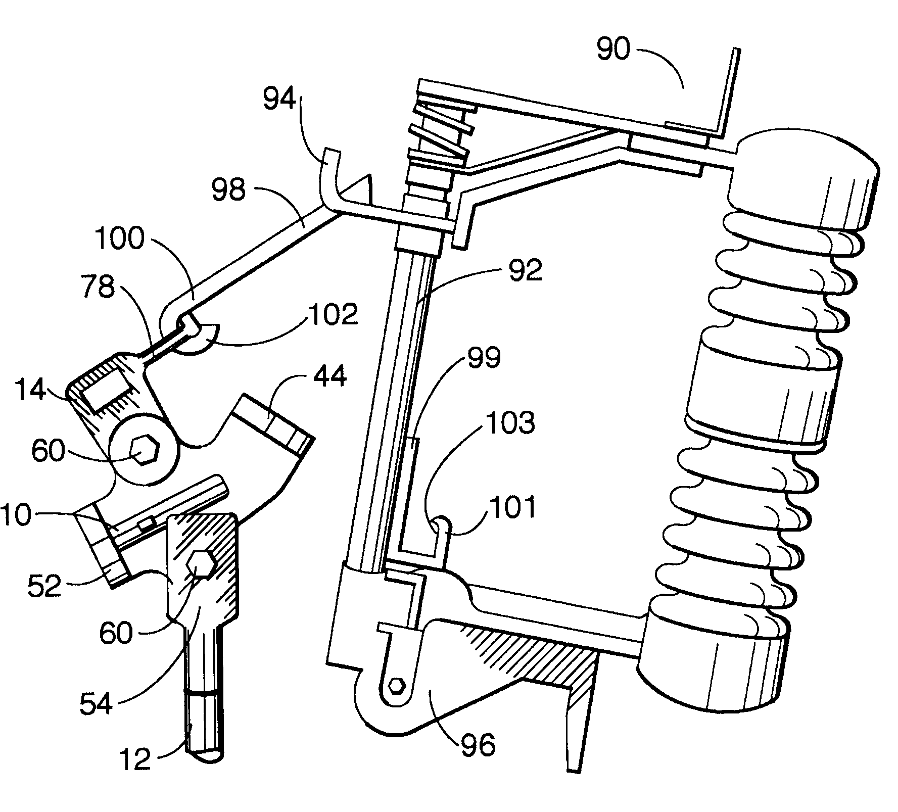
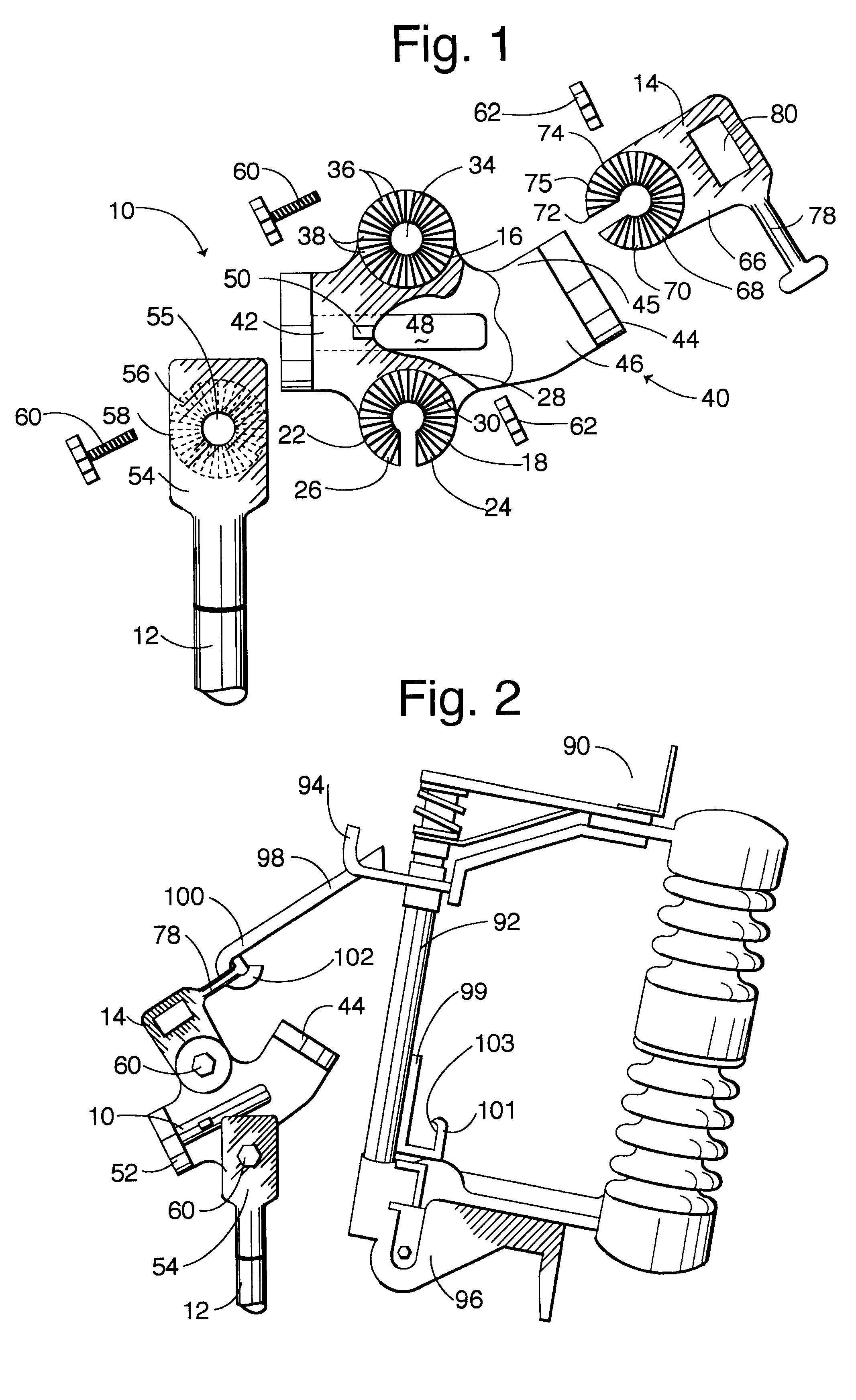
Referring now in more detail to the drawings in which like parts have like identifiers, FIG. 1 is a plan view, exploded and partially cut-away, of a transitional member 10 for attaching at a first angle between a distal end of a hook stick or elongate member 12 and a tool or tip 14, for orienting the tip 14 at a second angle relative to the elongate member, as discussed below. In the illustrated embodiment, the tip 14 is configured for operating electrical distribution equipment mounted on power poles in an electrical distribution system. The transitional member 10 comprises a body 16 having a first connector 18 for engaging a distal end of the elongate member 12. In the illustrated embodiment, the first connector 18 comprises a pair of arms 22, 24 that extend from the body 16 in a first direction to define a slot 26. As discussed below, a fastener passes through the slot 26 for securing the transitional member 10 to the elongate member 12. The first connector 18 defines a surface o...


PUM


Abstract

A method for moving operational catches on electrical distribution equipment mounted on poles of an electrical distribution system with a tool connected to a transitional member attached to an end of the pole, in which the transitional member connects at a first angle relative to the elongate member and at a second angle relative to the tool, with a light source in the transitional member oriented at an oblique angle for simultaneously illuminating a work area of the electrical distribution equipment and the tool, whereby the tool is illuminable by the light source even though the intermediate member is placed selectively in differing orientations relative to the elongate member.

Description

The present invention relates to actuators for operating electrical distribution equipment mounted on poles of electrical distribution systems. More particularly, the present invention relates to tips engaged to distal ends of elongate members for operating remote electrical distribution equipment mounted on poles of electrical distribution systems.Electrical transmission and distribution systems typically use a number of poles mounted along roadsides and other right-of-way for supporting electric lines. Electrical current transmits through the electric lines from generation stations for distribution to commercial and residential customers. Many of the poles include electrical distribution equipment for use controlling the transmission of electric current. These electrical distribution equipment include interrupt assemblies and transformers. The interrupt assemblies are typically reclosers, fuses, and cut-out switches. The interrupt assemblies are used to interrupt a transmission of...

Claims


Application Information

Patent Timeline
Patent Type & Authority Patents(United States)
IPC IPC(8): F16C11/10F16C11/04H01H85/02H01H85/00H01H31/00
CPCF16C11/10H01H85/0208Y10T403/32368H01H31/006
Inventor TAYLOR, DAVID G.
Owner TAYLOR MADDOX TECHN
Learn More