Center electrode assembly, nonreciprocal circuit device, and communication apparatus

a technology of center electrode and non-reciprocal circuit, which is applied in the direction of cathode ray tube/electron beam tube, electric discharge tube, instrument, etc., can solve the problems of difficult to form all center electrodes, limit the working accuracy available, and line may break

Inactive Publication Date: 2003-09-02
MURATA MFG CO LTD
View PDF8 Cites 4 Cited by
  • Summary
  • Abstract
  • Description
  • Claims
  • Application Information

AI Technical Summary

Benefits of technology

The nonreciprocal circuit device and a communication apparatus in accordance with the present invention have the center electrode assembly with the above-described features, thereby providing stable electrical characteristics and improving the reliability thereof.

Problems solved by technology

Such center electrodes are formed by press work using a mold or by etching work, but there are limits to the working accuracy available.
It is, therefore, difficult to form all center electrodes so as to have two lines, and currently, at least one of them is generally formed of one line.
However, in the conventional center electrode assembly 200 shown in FIGS. 30A and 30B, since each of the center electrodes has a small line width, there is the risk that a line may break due to vibration and heating during assembly or during operation of communication equipment in which the center electrode assembly is incorporated.
In particular, the line breakage of a center electrode formed of one line could cause a critical defect.
As indices of the performance of an isolator, there are insertion loss and isolation.
However, although this method can improve the insertion loss, this method reduces the isolation bandwidth, and is prone to increase the fraction of defective manufactured parts due to variations in characteristics among production lots of the center electrode assembly 240.

Method used


Image

  • Center electrode assembly, nonreciprocal circuit device, and communication apparatus
  • Center electrode assembly, nonreciprocal circuit device, and communication apparatus
  • Center electrode assembly, nonreciprocal circuit device, and communication apparatus

Examples


first embodiment

, FIGS. 1 to 4

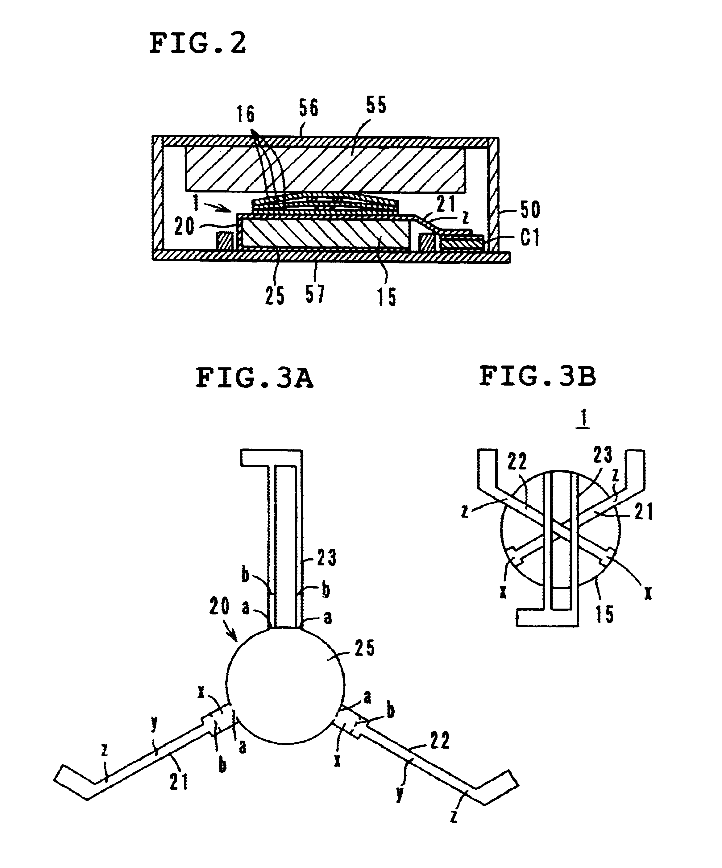
FIG. 1 illustrates each of the components of a nonreciprocal circuit device (concentrated-constant type isolator) having a center electrode assembly 1 in accordance with a first embodiment of the present invention, and FIG. 2 is a sectional view showing a state wherein these components have been assembled. FIG. 3A is a development view of an electrode assembly 20, and FIG. 3B is a view showing the center electrode assembly 1. Also, FIG. 4 is the electrical equivalent diagram of the nonreciprocal circuit device.

In this nonreciprocal circuit device, the center electrode assembly 1, which will be detailed below, a permanent magnet 55, matching capacitors C1, C2, and C3, and a resistor element R are accommodated in a resin case 50, and are surrounded by yoke portions, hereinafter referred to as metallic cases 56 and 57, from above and below.

In the resin case 50, a conductor portion for serving as an input / output terminal 51, the capacitor elements C1, C2, and C3, and the r...

second embodiment

, FIGS. 5A and 5B

A center electrode assembly 2 in accordance with a second embodiment of the present invention is configured by making the width of each of the center electrodes 21 and 22, which are each formed of one conductor line, so as to gradually increase (in a so-called reverse-tapered profile) from the center portion y up to the ferrite edge portion x on the cold-end side.

Other configurations of the second embodiment are the same as those of the above-described first embodiment, and the effects thereof also are fundamentally the same as those of the first embodiment. Furthermore, in the second embodiment, since the line width of the center electrodes 21 and 22 constitutes a so-called reverse tapered profile, no step difference occurs at the ferrite edge portion x on the cold-end side. Notably, this allows the stress concentration at the folded portion "b" to be avoided, thereby stabilizing even more the crossing angle formed among the center electrodes 21, 22, and 23 on the ...

third embodiment

, FIGS. 6A and 6B

A center electrode assembly 3 in accordance with a third embodiment is configured by making the width of each of the center electrodes 21 and 22, which are each formed of one conductor line, so as to gradually increase (in a so-called reverse-tapered profile) from the center portion y up to the ferrite edge portion x on the cold-end side, as well as up to the ferrite edge portion z on the hot-end side.

Other configurations of the third embodiment are the same as those of the above-described first and second embodiments, and the effects thereof also are fundamentally the same as those of the first and second embodiments.

In the third embodiment, the ferrite edge portion on the hot-end side z is also formed wide. As shown in FIG. 2, this edge portion z forms an angle of about 45.degree. with the center portion y, and hence, if the line width here were small, the bending angle and bending shape thereof would not be stabilized, and could cause connection defects or line b...


PUM


Abstract

A center electrode assembly, a nonreciprocal circuit device, and a communication apparatus are provided which have stable physical properties and high reliability, and which eliminate the risk of line breakage of the center electrodes thereof. The center electrode assembly includes an electrode assembly wherein a plurality of center electrodes extend outward from the center planar portion (ground electrode) thereof at a predetermined angular distance; and a ferrite. The center planar portion is abutted against the bottom surface of the ferrite, then the center electrodes are wrapped around the top surface of the ferrite across the side surface thereof, and these center electrodes are crossed with one another on the top surface of the ferrite. At least one center electrode is formed of one line, and the line width of the center electrode is set to be partly larger at the ferrite edge portion on the cold-end side.

Description

1. Field of the InventionThe present invention relates to a center electrode assembly and a nonreciprocal circuit device which may constitute an isolator or a circulator for use in, for example, a microwave band, and relates to a communication apparatus including this nonreciprocal device.2. Description of the Related ArtA center electrode assembly shown in FIGS. 30A and 30B is known for use in a concentrated-constant type isolator (nonreciprocal circuit device) adopted in mobile communication equipment such as mobile telephones. This center electrode assembly 200 is formed by wrapping a disk shaped microwave ferrite 201 in an electrode assembly 210 including three center electrodes 211, 212, and 213.The electrode assembly 210 is formed by extending outward the center electrodes 211, 212, and 213 at predetermined angles from the center planar portion (ground electrode) 215. The center electrodes 211 and 212 are formed of one line, while the center electrode 213 is formed of two line...

Claims


Application Information

Patent Timeline
Patent Type & Authority Patents(United States)
IPC IPC(8): H01P1/387H01P1/32H01P1/36H01P1/383
CPCH01P1/387
Inventor OHIRA, KATSUYUKIHASEGAWA, TAKASHI
Owner MURATA MFG CO LTD
Why Eureka
Try Eureka