Draining structure for diving mask

a technology for diving masks and structures, applied in underwater equipment, goggles, protective garments, etc., can solve the problems of affecting the breathing and vision of the diver, affecting the diver's breathing, so as to reduce the vertical openness of the transverse opening, not deformed, and increase the compression strength

Inactive Publication Date: 2003-07-29
HSIEH HSING CHI
View PDF6 Cites 20 Cited by
  • Summary
  • Abstract
  • Description
  • Claims
  • Application Information

AI Technical Summary

Benefits of technology

It is therefore a primary object of the present invention to provide an improved draining structure for diving masks to eliminate the drawbacks existing in the conventional structure by guiding the air bubbles produced by the diver's expiration to two lateral sides of the diving mask, preventing the valve leaf from being sideward opened, and protecting the water passage against deformation when the soft head cover is put on the diver's head.
The draining guide of the present invention is characterized by a hole located directly below the valve leaf. When a diver wearing the diving mask of the present invention jumps into water in a vertical position, an instantaneous water pressure produced at the instant of contact of the diving mask with water surface will fully act on a bottom side of the valve leaf via the hole on the draining guide to therefore further push the valve leaf upward to tightly close the through hole on the valve seat without the problem of sideward opening of the valve leaf.
The draining guide of the present invention is also characterized by an upward projected transverse flange provided along a rear end of the water passage to reduce a vertical openness of a transverse opening at a rear end of the water passage and to intercept air bubbles produced by the diver's expiration at the transverse opening, lest the air bubbles should move through the bottom to the front of the diving mask to interfere with the diver's vision.
The flange provided along the rear end of the water passage also reinforces the water passage at the transverse opening, so that the two side outlets of the water passage have increased compression strength and are not deformed and narrowed by the head cover when the latter is put on the diver's head and outward stretched to press against the side outlets, allowing the air bubbles to smoothly and quickly move out of the diving mask via the side outlets.

Problems solved by technology

Since the head cover does not always fit with the diver's head contour, there are frequently clearances left between the diving mask and the diver's face, resulting in invasion of water into the diving mask to interfere with the diver's face or even seriously affecting the diver's breath and vision.
Since the draining valve is provided below the nose portion at a central bottom of the diving mask, the air bubbles in the drained water tend to move upward in front of the diving mask and seriously interfere with the diver's vision.
This is, of course, very inconvenient to the diver.

Method used


Image

  • Draining structure for diving mask
  • Draining structure for diving mask
  • Draining structure for diving mask

Examples


Embodiment Construction

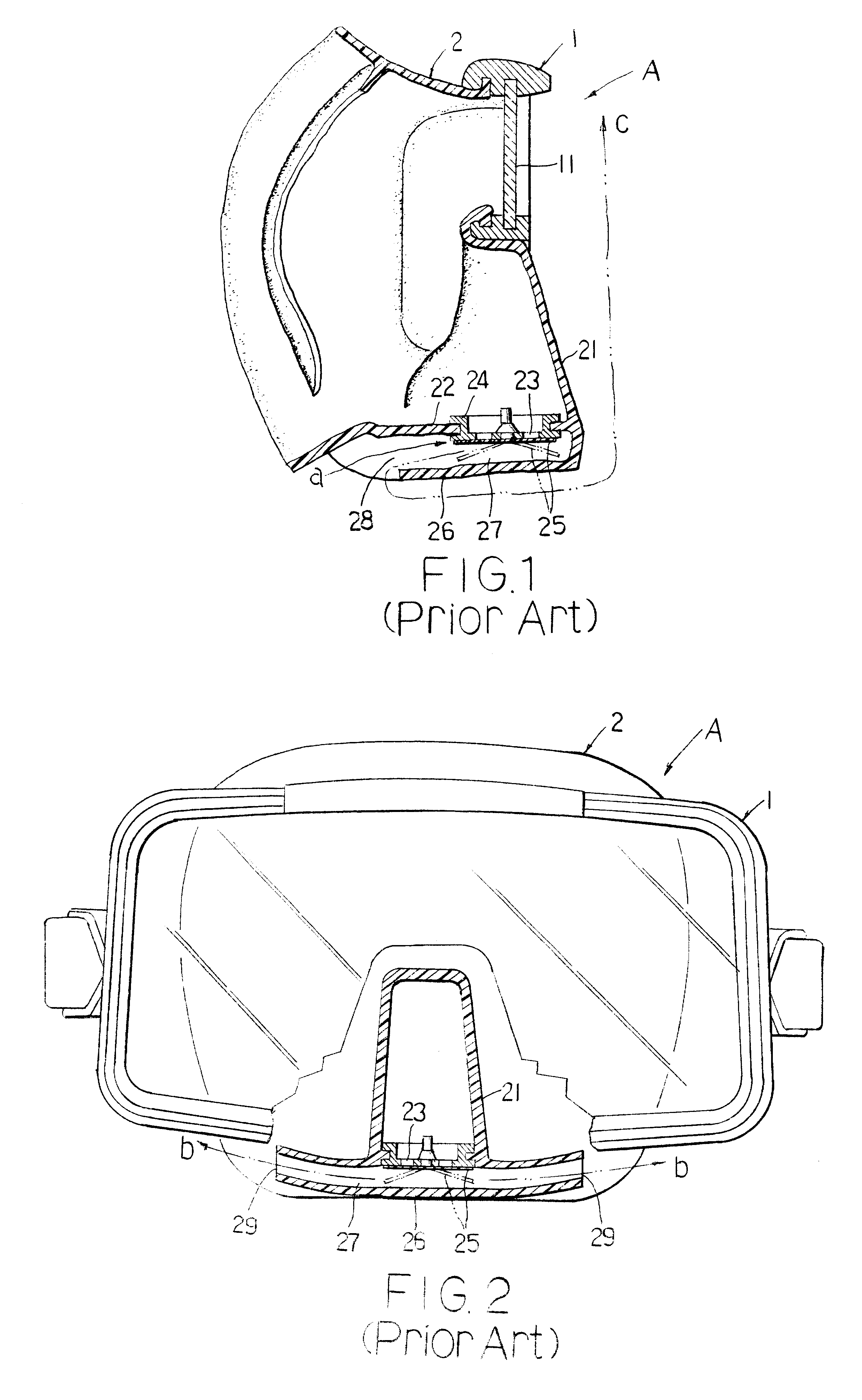
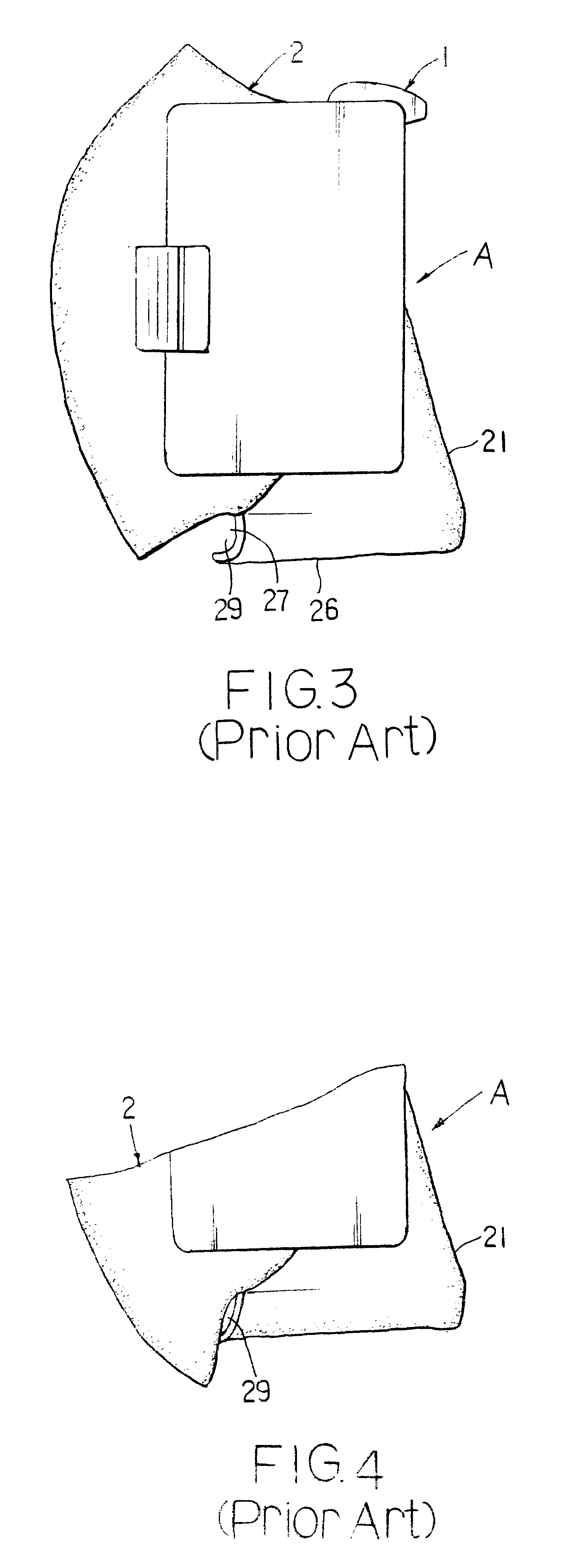
Please refer to FIGS. 5, 6, and 7 that are sequentially a bottom view, a sectioned side view, and a partially sectioned front view of a diving mask B according to the present invention. As shown, the diving mask B includes a rigid skirt 1 framing a lens 11, and a soft head cover 2 fixedly connected to the skirt 1. The soft head cover 2 includes a forward projected nose portion 21. A valve seat 24 having a through hole 23 is mounted on a bottom 22 of the nose portion 21. A valve leaf 25 is mounted on the valve seat 24 to locate below the through hole 23. The valve seat 24 and the valve leaf 25 together form a one-way draining valve to be opened in an outward direction only. The valve leaf 25 normally closes the through hole 23 to prevent external water from invading into the diving mask B via the through hole 23. When a diver wearing the diving mask B expires via his or her nose, the valve leaf 25 is blown outward to open the through hole 23, allowing any water accumulated in the div...


PUM


Abstract

A draining structure for diving mask includes a soft head cover fixedly connected to a rigid skirt framing a lens. The soft head cover includes a forward projected nose portion having a draining valve provided at a bottom thereof to be openable only in an outward direction. A draining guide is provided below the nose portion and has a hole formed directly below the draining valve to prevent water from sideward flushing open the draining valve when a diver jumps into water in a vertical position. An upward projected flange is provided at a rear end of the draining guide to guide air bubbles produced by the diver's expiration to two side outlets of the draining guide. The flange also reinforces the two side outlets and prevents them from deformation when the head cover is put on the diver's head and presses against the side outlets.

Description

FIELD OF THE INVENTIONThe present invention relates to a draining structure for a diving mask, and more particularly to a draining structure for a diving mask that is able to drain off water accumulated in the diving mask via two side outlets at a rear end of the diving mask, to prevent water from sideward flushing open a valve leaf and entering the diving mask, and to protect the side outlets from deformation when the diving mask is put on a diver's head.BACKGROUND OF THE INVENTIONA diving mask typically includes a rigid skirt framing a lens, and a soft head cover fixedly connected to the rigid skirt for putting on a diver's head. Since the head cover does not always fit with the diver's head contour, there are frequently clearances left between the diving mask and the diver's face, resulting in invasion of water into the diving mask to interfere with the diver's face or even seriously affecting the diver's breath and vision. It is therefore necessary to timely drain off water accu...

Claims


Application Information

Patent Timeline
Patent Type & Authority Patents(United States)
IPC IPC(8): B63C11/12B63C11/02
CPCB63C11/12
Inventor HSIEH, HSING-CHI
Owner HSIEH HSING CHI
Why Eureka
Try Eureka