
Power distribution arrangement for an injet printhead

a technology of power distribution arrangement and injet printhead, which is applied in printing and other directions, can solve the problems of power consumption, limited nozzle packing density, and insufficient power consumption to meet the requirements of application

Inactive Publication Date: 2003-07-15
SILVERBROOK RES PTY LTD +1
View PDF10 Cites 9 Cited by
  • Summary
  • Abstract
  • Description
  • Claims
  • Application Information

AI Technical Summary

Benefits of technology

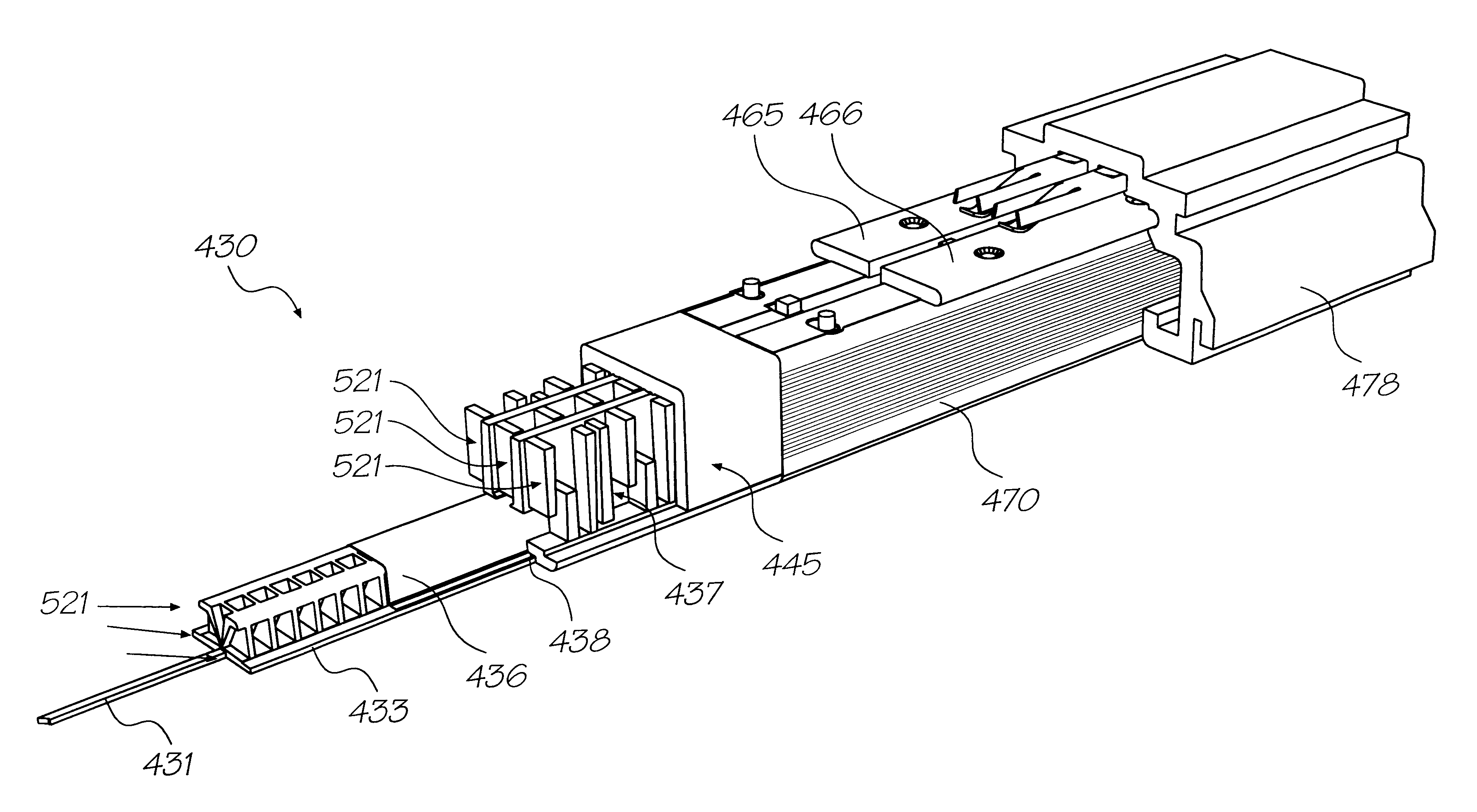
The housing may include a series of positioning protuberances for accurately locating the power supply busbars and flexible interconnect means therewith.

Problems solved by technology

This is because the two main contenders--thermal ink jet and piezoelectric ink jet--each have severe fundamental problems meeting the requirements of the application.
The most significant problem with thermal ink jet is power consumption.
This is approximately 100 times that required for these applications, and stems from the energy-inefficient means of drop ejection.
The high power consumption limits the nozzle packing density, as
The most significant problem with piezoelectric ink jet is size and cost.
This is not a significant problem at the current limit of around 300 nozzles per print head, but is a major impediment to the fabrication of page width print heads with 19,200 nozzles.

Method used


Image

  • Power distribution arrangement for an injet printhead
  • Power distribution arrangement for an injet printhead
  • Power distribution arrangement for an injet printhead

Examples


Embodiment Construction

The preferred embodiment is a 1600 dpi modular monolithic print head suitable for incorporation into a wide variety of page width printers and in print-on-demand camera systems. The print head is fabricated by means of Micro-Electro-Mechanical-Systems (MEMS) technology, which refers to mechanical systems built on the micron scale, usually using technologies developed for integrated circuit fabrication.

As more than 50,000 nozzles are required for a 1600 dpi A4 photographic quality page width printer, integration of the drive electronics on the same chip as the print head is essential to achieve low cost. Integration allows the number of external connections to the print head to be reduced from around 50,000 to around 100. To provide the drive electronics, the preferred embodiment integrates CMOS logic and drive transistors on the same wafer as the MEMS nozzles. MEMS has several major advantages over other manufacturing techniques:

mechanical devices can be built with dimensions and ac...


PUM


Abstract

An ink supply unit for supplying separate color inks to a portable ink jet print head, the ink supply unit including: a slot for insertion of the printhead; a series of elongated chambers for the storage of the separate color inks, the chambers being interconnected with the slot for the supply of ink to the printhead; a series of conductive rails along the outside of the ink supply unit, each conductive rail interconnected to a power supply at a series of points along the conductive rail; a tape automated bonding strip along the outside of the ink supply unit having a series of control lines along one surface thereof for mating with a corresponding external series of control lines, the tape automated bonding strip further having a repeating series of interconnects to the printhead, the interconnects interconnecting the control lines and the conductive rails to the printhead. The unit can be detachable from the power supply and the external series of control lines.

Description

The present invention relates to a power distribution arrangement for an inkjet printhead and in the preferred form to incorporation of such an arrangement as part of the ink supply unit.The invention has been developed primarily for use in a pagewidth printer utilizing a printhead chip and will be described with reference to such a device. However it will be appreciated that the invention can be applied to other printer types and configurations.Recently, for example, in PCT Application No. PCT / AU98 / 00550 the present applicant has proposed a pagewidth inkjet printing device which utilizes micro-electromechanical (MEMS) processing techniques in the construction of a thermal bend actuator type device for the ejection of fluid from a nozzle chamber.With any compact but fragile page width printhead, substantial currents must be supplied to the printhead whilst printing. This is especially the case where an extremely large number of ink ejection nozzles are utilized.Additionally, a pagew...

Claims


Application Information

Patent Timeline
IPC IPC(8): B41J2/05B41J2/14B41J2/16
CPCB41J2/0452B41J2/04528B41J2/04541B41J2/04543B41J2/04553B41J2/04563B41J2/0457B41J2/04585B41J2/04588B41J2/04591B41J2/04596B41J2/04598B41J2/14B41J2/14427B41J2/16B41J2/1623B41J2/1628B41J2/1631B41J2/1632B41J2/1635B41J2/1637B41J2/1639B41J2/1642B41J2/1646B41J2/1648B41J2002/14491
Inventor SILVERBROOK, KIA
Owner SILVERBROOK RES PTY LTD
Learn More