
Image recording body and image forming device using the image recording body

a technology of image recording and forming device, which is applied in thermography, instruments, photosensitive materials, etc., can solve the problems of high efficiency of light-heat conversion of light source, time-consuming writing for the above method, and use of expensive devices as light sources, so as to improve light-heat conversion efficiency

Inactive Publication Date: 2003-07-08
RICOH KK
View PDF52 Cites 5 Cited by
  • Summary
  • Abstract
  • Description
  • Claims
  • Application Information

AI Technical Summary

Benefits of technology

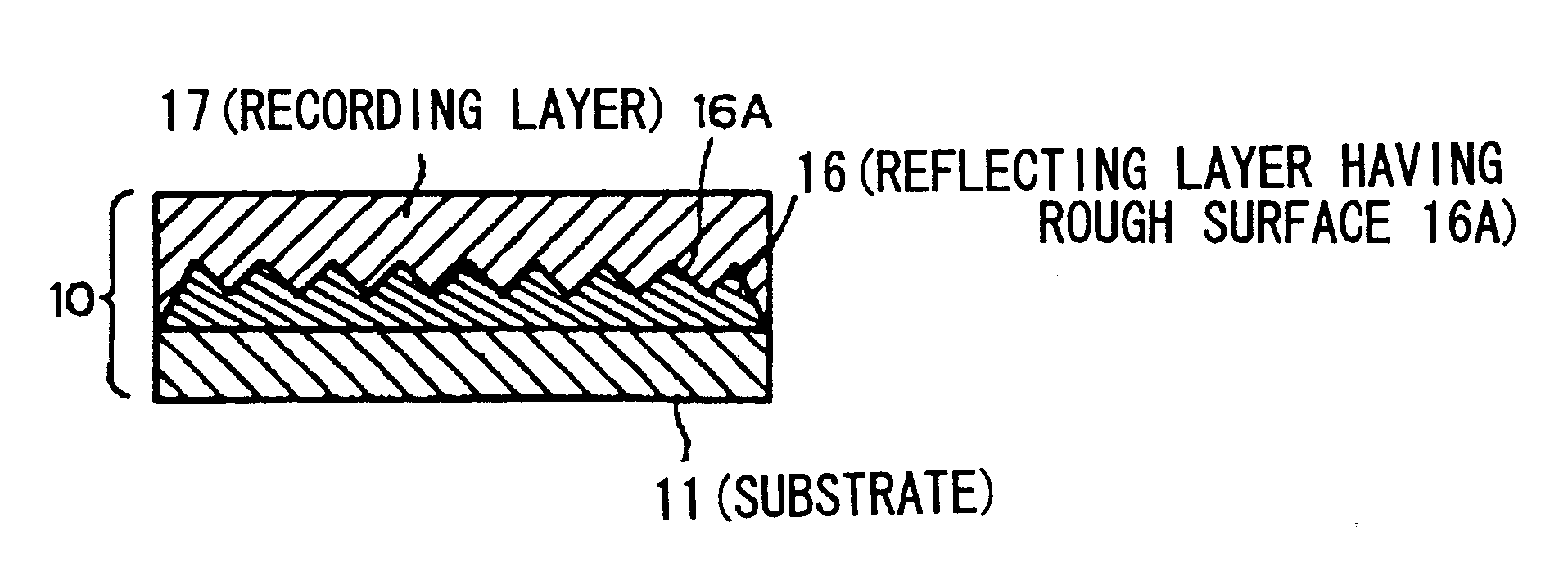
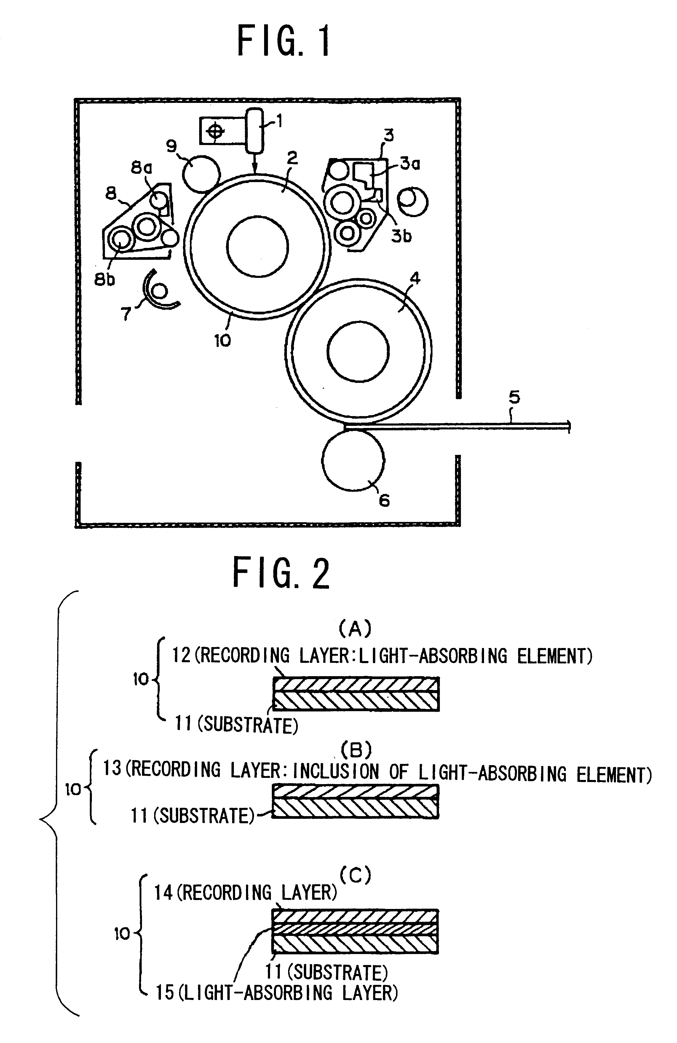
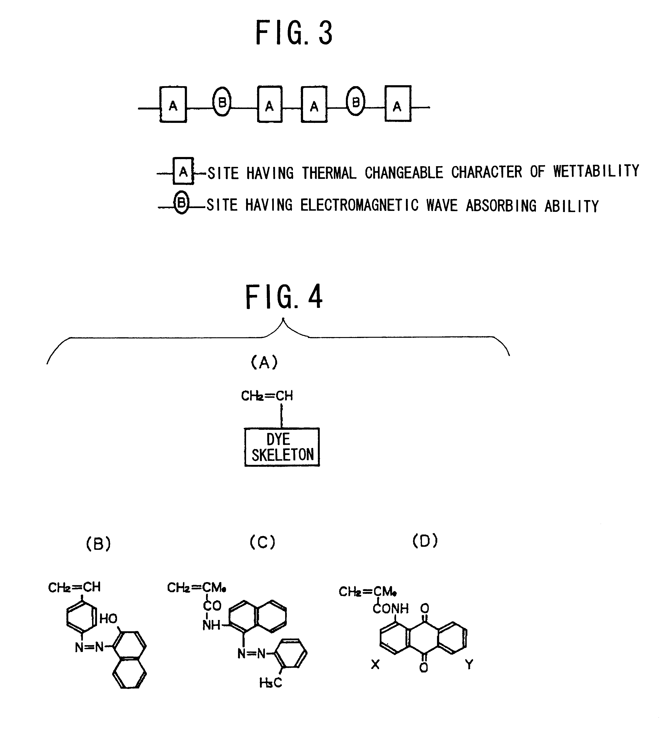
A technical feature of the present invention resides in an image recording body comprising an element, which absorbs light (which includes an electromagnetic wave) in response to image information to achieve recording, provided in a recording layer of the image recording body formed on an uppermost layer thereof comprising a material having thermal changeable character of wettability, or in a substrate of said image recording body or an intermediate layer thereof, thereby improving a light-heat conversion efficiency in the light-stimulated writing.
In the above invention, by providing a disk-like mass member having a weight equal to or more than that of the rotating multi-face mirror for the motor or a rotating axis of the rotating multi-face mirror, the rotation of the multi-face mirror can be stabilized at the low rate, so that lesser irregularities of an image density, dot and a line size (for example, broadening or narrowing) can be obtained to provide an inexpensive light scanning apparatus.

Problems solved by technology

Also, for the recording method by negative writing described in the above patent application No. 8-276663, an efficiency of light-heat conversion of a light source is not enough high because of continuous oscillation of the light source.
There are problems that writing for the above method is time-consuming and is required to employ an expensive device as the light source.
Further, in the recording method disclosed in the above patent application No. 8-276663, there are disadvantages that a lifetime of the light source is shorter as compared to positive writing.
This results in spreading of exposed areas and a recording irregularity, such as a moire.
In addition, in order to reuse the recording body used once, a clear printing can not be performed with a recording paper fouled by the remaining ink unless the ink remaining on the recording body is removed completely.
Furthermore, in a case of writing to the recording body by use of a plurality of heating means, if only one of the heating means is broken, a non-image region which is not heated is produced, thereby giving rise to a line of scumming.
In a case where negative writing is also carried out, an irregularity in heating and cumulative heat of an image forming means during negative writing operation cause the image to be degraded.
In a case where negative writing is also performed through a rotating multi-face mirror, if sensitivity of the recording body is low, a rotation rate of the rotating multi-face mirror must be low, so that the rotation rate is unstable because of the absence of an action of inertia induced by the rotation.
This result in an irregularity of the light-heat conversion, thus producing irregularities relating to an image density, dot size and dot line.

Method used


Image

  • Image recording body and image forming device using the image recording body
  • Image recording body and image forming device using the image recording body
  • Image recording body and image forming device using the image recording body

Examples


example

Under the same condition as the above example and by using the same image forming means and the same method for adjusting heating amount as the above example, writing was carried out. As a result, an influence of the temperature irregularities produced in the pixel of interest can be inhibited according to the heating state of the adjacent pixel, thereby producing high quality image.

FIG. 33 shows a schematic view to explain other embodiment according to the present invention. Since the influence of the temperature irregularities produced in the pixel of interest according to heat records of a plurality of lines written already so that the high quality image can be produced, the heating amount for writing can be changed according to the heat records of the plurality of lines which are written already and are in the same main scanning direction or in a near scanning direction.

FIG. 33 shows an example of a case where pixels in the main scanning direction are written at the same time, c...


PUM

PropertyMeasurementUnit
roughnessaaaaaaaaaa
thicknessaaaaaaaaaa
thicknessaaaaaaaaaa

Abstract

There is provided improvement of a light-heat conversion in a light-stimulated writing method.An image recording body includes an element, which absorbs light (electromagnetic wave), provided in a surface of a recording body 10, or in a recording layer formed on uppermost layer of the recording body having a material exhibiting thermal changeable character of wettability, or in a substrate or an intermediate layer of the recording body. After a liquid is on the recording body 10 by a liquid forming means 3, light-stimulated writing is carried out. When the light-stimulated writing is carried out with light (electromagnetic wave) from a light (electromagnetic wave) source according to image information, an efficiency of light-heat conversion can be enhanced by a light (electromagnetic wave)-absorbing element.

Description

The present invention relates generally to an image recording body and an image forming apparatus by use of the image recording body, and more particularly to a structure of the image recording body in order to form a latent image by means of a light (or heat)-stimulated writing method, improvement of a light-to-heat conversion efficiency during a light-stimulated writing operation, a long-life operation of a source for writing, an adjustment of a light (or heat) amount during the light-stimulated writing operation, a method for removing an ink remaining on the image recording body and a method for forming the latent image thereon.FIG. 1 illustrates a schematic view of an essential part of an image forming apparatus of an embodiment according to the present invention. As shown in FIG. 1, the image forming apparatus comprises a heating source 1, a recording roller 2, an inking unit 3, an intermediate transfer roller 4, a recording paper 5, a pressure roller 6, an infrared heater 7, a...

Claims


Application Information

Patent Timeline
Patent Type & Authority Patents(United States)
IPC IPC(8): B41J2/00B41J2/32B41J2/475B41J2/355B41M5/36B41J11/00B41M5/42B41N3/00B41M5/40B41M5/41B41M5/00B41J2/325B41J2/315B41M5/26G06K15/02
CPCB41C1/1041B41J2/00B41J2/32B41J2/355B41J2/4753B41J11/0015B41M5/368B41M5/41B41M5/42B41N1/14B41N3/006B41N3/08G06K15/029B41C1/1075B41J2/475G06K2215/0085Y10S430/165
Inventor KATANO, YASUOTOMITA, SATORUMORIKAWA, MINORUHARA, KEI
Owner RICOH KK
Learn More