
Device and method of plaining glasses or glass-ceramics

a technology of glass-ceramics and plaining devices, applied in glass blowing equipment, glass shaping equipment, furnace types, etc., can solve the problems of reducing the plaining time or eliminating, requiring especially high temperatures, and affecting the effect of the plaining process

Inactive Publication Date: 2003-07-08
SCHOTT AG
View PDF19 Cites 23 Cited by
  • Summary
  • Abstract
  • Description
  • Claims
  • Application Information

AI Technical Summary

Benefits of technology

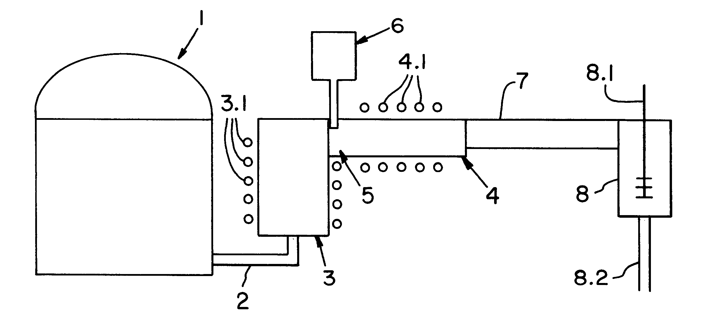
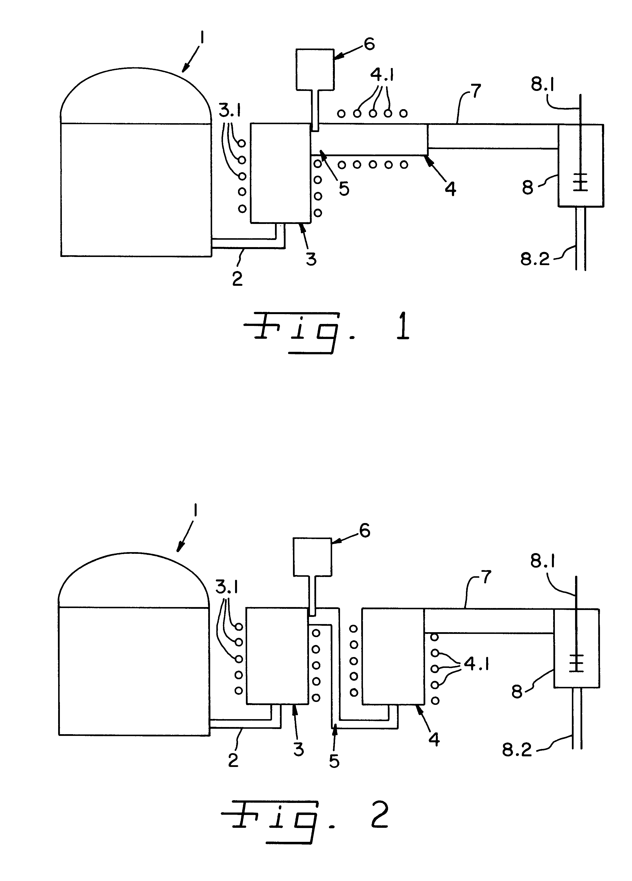
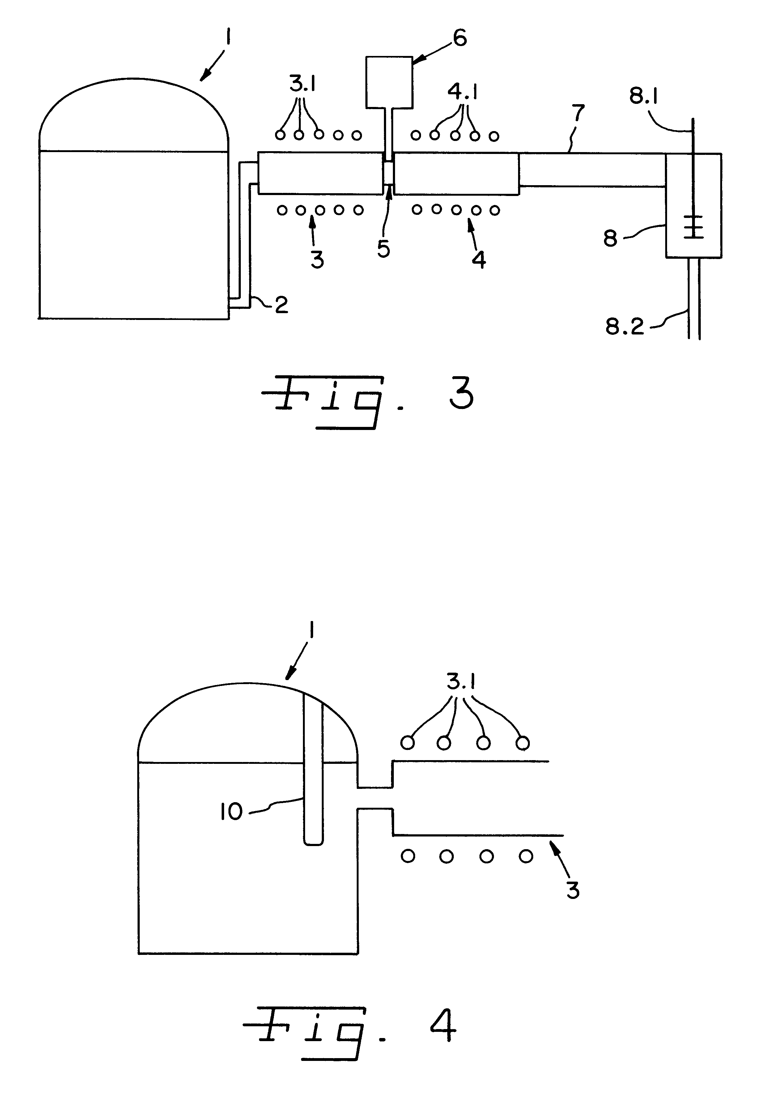
This problem is solved by the features of the independent claims. The inventor has recognized that the plaining process can be designed to be significantly more efficient if it is not carried out in a single container, but rather in at least two containers connected in series. The quality of the glass is distinctly improved again if the melt is not only heated in the first plaining container to very high temperatures and then cooled off, but rather reheated in a second container and then allowed to cool off.
There is also the possibility, by connecting two plaining zones in series, that by allowing the two plaining processes that are taking place there to develop under different conditions and of using different plaining means at different locations additional benefits may be created.

Problems solved by technology

The plaining process requires especially high temperatures.
Thus, high-temperature plaining creates the possibility of either drastically lowering the plaining time or of eliminating the addition of plaining media for producing large plaining bubbles.
However, this arrangement is less favorable then the arrangement described here with two or more genuine plaining units separated spatially from the melting crucible due to the flow conditions, batch charges, solids mixture charges, and glass discharges the movement of the glass mass acts against the upward movement of the bubbles and draws rising bubbles repetitively down again and again.
Moreover, in this instance the bubbles would have to penetrate the cold batch top surface, which is normally not successful, or the surface would have to be allowed to melt plain and clear in the meantime, which opposes a high throughput and is thus uneconomical.
In the case of glasses with high viscosity a plaining can not be expected in any case since the bath depth is too great for a rise of bubbles in a glass with high viscosity and thus having a low rising rate.
The plaining glass must be meltable at low temperatures since high temperatures generally result in an undesired, premature consumption of the plaining medium.

Method used


Image

  • Device and method of plaining glasses or glass-ceramics
  • Device and method of plaining glasses or glass-ceramics
  • Device and method of plaining glasses or glass-ceramics

Examples


example 2 (

Several glasses from the same system are collated here that vary in the concentrations of the individual oxides. The indicated limits follow from the concrete class compositions and do not represent any basic limitation):

example 2

Example 3

The cited glasses are to be understood as merely exemplary embodiments. A plurality of other glasses are also conceivable that can be used instead of the cited ones without making any basic changes to the method.

If the quality of the glass so requires, a series of any desired number of plaining crucibles is conceivable and the adjusting of as many good glass qualities as desired is possible in this manner. The optimizing factor here is the cost-effectiveness ratio since every further plaining stage not only produces an improvement of the quality but also additional expense. However, any required quality can be adjusted with the concept of cascade plaining.

In all instances described the walls of the plaining units are built up from liquid-cooled, metallic tubes or air-cooled, ceramic parts that are of such a nature that they are transparent for electromagnetic radiation in the frequency range of 10 kHz to 5 MHz.

The plaining zones are heated by radiating high-frequency energy...


PUM

PropertyMeasurementUnit
Temperatureaaaaaaaaaa
Areaaaaaaaaaaa
Melting pointaaaaaaaaaa

Abstract

A device and method for the plaining of glasses or glass-ceramics. The device is provided with a melting vat, at least two plaining containers serially connected after the outlet of the melting vat, and at least one of the plaining containers is built in accordance with the skull principle from a plurality of metal tubes comprising a cooling agent connection and a high-frequency device for inductively coupling high-frequency energy into the contents of the plaining container.

Description

1. Field of the InventionThe invention is relative to a device and a method of plaining in the art of glass manufacturing, or glass ceramics.2. Description of the Related ArtMelting vats of continuous glass-melting furnaces are operated for the continuous plaining of glass that have a melting range, a plaining range and a standing and homogenizing range. The actual degassing of the glass melt customarily takes place in the plaining zone. Redox reactions or evaporation effects take place here that result in the formation of bubbles and in the inflating of present bubbles. The temperature in the plaining zone is selected to be as high as possible in order that the bubbles can rise rapidly to the surface of the melt and that the melt becomes bubble-free. Classic vats are limited thereby to maximum admissible temperatures in a plaining range of 1650.degree. C. on account of the wall material, that consist (as a rule) of fire-resistant ceramics or platinum or platinum alloys.Numerous dev...

Claims


Application Information

Patent Timeline
IPC IPC(8): C03B5/225C03B5/00C03B5/185C03B5/02
CPCC03B5/021C03B5/185C03B5/225C03B2211/70C03B2211/71C03C3/062C03C3/091C03C3/247
Inventor KIEFER, WERNERKOLBERG, UWEROMER, HILDEGARDSCHMITT, STEFANSCHMIDBAUER, WOLFGANG
Owner SCHOTT AG
Learn More