
Techniques for automatically providing a high-resolution rendering of a low resolution digital image in a distributed network

Inactive Publication Date: 2003-06-10
MONUMENT PEAK VENTURES LLC
View PDF10 Cites 236 Cited by
  • Summary
  • Abstract
  • Description
  • Claims
  • Application Information

AI Technical Summary

Benefits of technology

Other attempts have been made that try to remedy the problem outlined above, but with limited success. The Internet Imaging Protocol (IIP) has been developed that provides for optimized access and display of a FlashPix files over the network. When using IIP, a FlashPix file that resides on a serve can be efficiently rendered. A client (i.e. Web browser) must contain executable code (such as a Java applet, ActiveX control, or browser plug-in) that allows it to request portions of the FlashPix file. This involves downloading of fully rendered tiles or portions of the image at different resolutions. While this does provide for efficient display of a FlashPix file over a low bandwidth network connection, it does not solve the generate problem of linking the low-resolution resultant image file back to the high-resolution digital negative and edit list. IIP is simply a method for serving up and viewing large FlashPix files over the network in an efficient manner.
Other variants of FlashPix exist, including LivePicture's FITS technology. The FITS format allows the image operations to be performed on low-resolution image data and saved, thus eliminating the need to do a time consuming render of the high-resolution image data when saving the file. The re-rendering at high resolution is done once the output resolution is determined. However, it does not solve the general problem of linking the low-resolution resultant image file back to the high-resolution digital negative and edit list.

Problems solved by technology

Since most imaging applications only perform image operations on one resolution, usually the highest resolution, these operations are sometimes very slow, even on the fastest computers.
While this is one option, this is not desired since it would not be possible to obtain an image rasterized at a higher resolution.
Unfortunately, it is not possible for the application to know apriori how the image will be used in the future, thus a high-resolution image is usually created.
While this appears to resolve the problems listed above, there are several limitations.
Further, the image transforms supported are limited to a few operations.
Other attempts have been made that try to remedy the problem outlined above, but with limited success.
While this does provide for efficient display of a FlashPix file over a low bandwidth network connection, it does not solve the generate problem of linking the low-resolution resultant image file back to the high-resolution digital negative and edit list.
However, it does not solve the general problem of linking the low-resolution resultant image file back to the high-resolution digital negative and edit list.

Method used


Image

  • Techniques for automatically providing a high-resolution rendering of a low resolution digital image in a distributed network
  • Techniques for automatically providing a high-resolution rendering of a low resolution digital image in a distributed network
  • Techniques for automatically providing a high-resolution rendering of a low resolution digital image in a distributed network

Examples


first embodiment

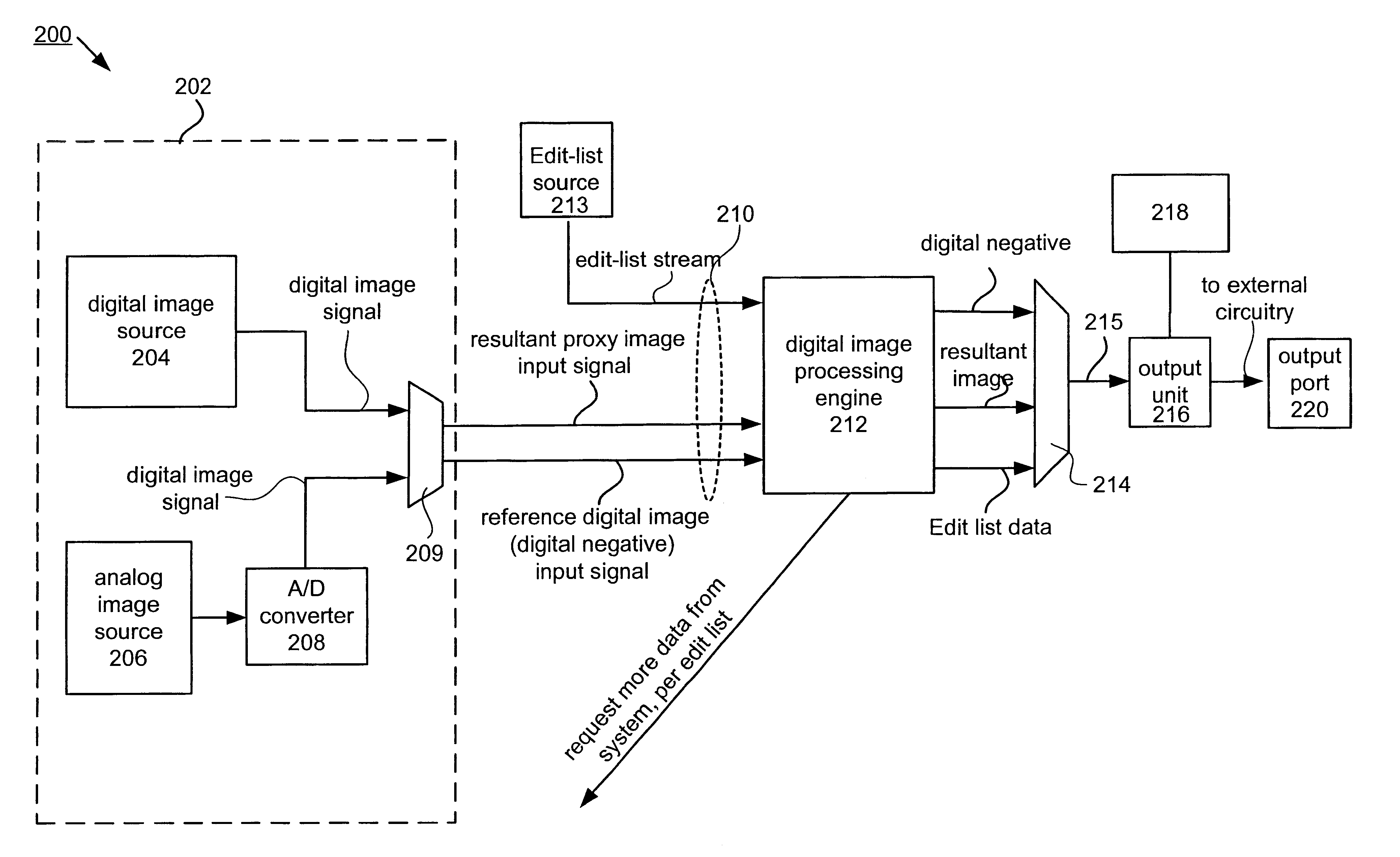
It should be realized that an "edit list" can take the form of a variety of different embodiments, three of which are described below. This is meant to describe different variants of an edit list, but not an all-inclusive list. The first embodiment is a list that describes a set of individual operations that are to be performed on a given photo. These edit operations can be applied to a photo to generate the resultant image at the desired output resolution. The advantage of this structure is that new edits can be added to the end of the list or removed from the end of the list through an "undo" operation. A first sample piece of XML code is included for illustrative purposes:

href="www.pictureiq.com / samples / nicholas.jpg" content-type="image / jpeg" / >

An alternative embodiment is to use this list to represent a state description of each operation applied to the photo, in which certain operations can be turned on ...

third embodiment

A third embodiment combines the benefits of the first two embodiments. The edit list not only represents the state description of operations, but also includes the ability for one or more of the operations that are part of the state description to be a list of individual operations that are to be applied to the photo, thus merging the two methods

It should be noted, this architecture also allows an application to describe access to multiple resolutions of a digital negative from a single file. For example, multiple resolutions of the same image (at different resolution) could be externally linked via the "edit list" that describes the cross-reference between the various distributed image files. In this case, the "edit list" is the "glue" that holds the structure indicative of how each file is interrelated, but not necessarily the "script" that describes additional editing operations, here the "script" portion of the edit list is empty or null. For example, in one implementation, the ...


PUM


Abstract

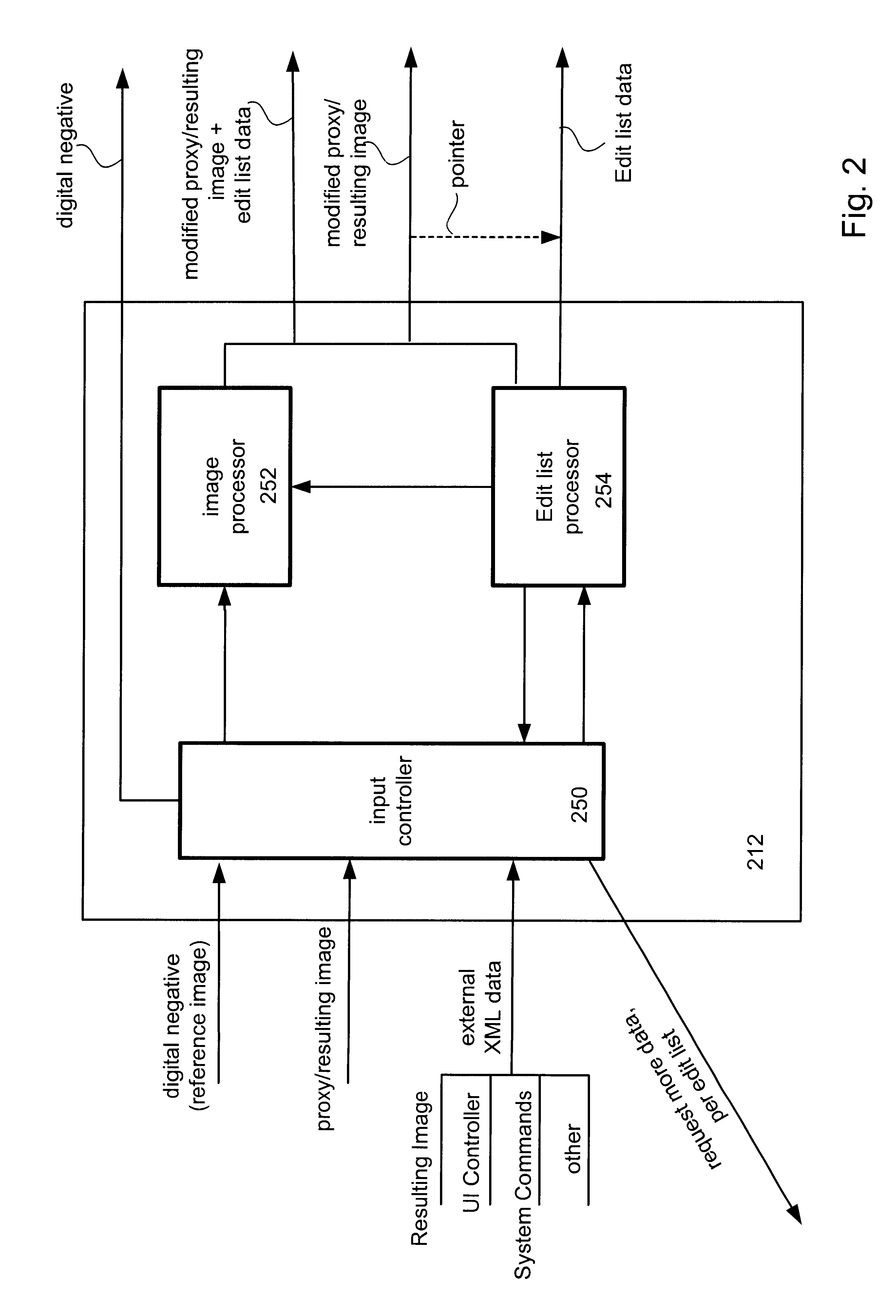
In one embodiment, a method of providing a recipient of a low-resolution digital image a way to automatically obtain a high-resolution rendering of the digital image is disclosed. In one embodiment, in a distributed system having a first node coupled to a second node, a method of outputting at the first node a composited digital image at a selected resolution is disclosed. At the second node, the composited digital image at a first resolution is generated and the composited digital image is then converted to a second resolution. The converted composited digital image is then transferred to the first node where the selected resolution is determined. If the selected resolution is the first resolution then the composited digital image is fetched and the composited digital image is then output at the first resolution. If, however, it is determined that the selected resolution is the second resolution, then the composited digital image is output at the at the second resolution.

Description

1. Field of InventionThe invention relates generally to digital image processing systems. More particularly, methods and apparatus for selectively processing a digital image are disclosed. More particularly, the invention provides techniques that provides a recipient of a low-resolution composited digital image (such as a greeting card or calendar) a way to automatically obtain a high-resolution rendering of the received composited digital image.2. Description of Relevant ArtWhen a user performs image operations using digital image processing programs such as Adobe Photoshop.TM. or PhotoDeluxe.TM., image operations are performed directly on the raw pixels of the image. Since most imaging applications only perform image operations on one resolution, usually the highest resolution, these operations are sometimes very slow, even on the fastest computers. If an application could work at a lower resolution for display purposes, the processing time would significantly decrease, thus incre...

Claims


Application Information

Patent Timeline
IPC IPC(8): G06F17/30
CPCG06F17/30905G06F16/9577
Inventor CROSBY, MATTWILKINS, DAVID C.
Owner MONUMENT PEAK VENTURES LLC
Learn More