
Device for monitoring voltage leads and method of using same

a voltage lead and device technology, applied in the field of electric arc welding technology, can solve the problems of overheating of the electrode, distorted command signal, and power source termination of the weldinger, and achieve the effect of easy implementation

Inactive Publication Date: 2003-05-27
LINCOLN GLOBAL INC
View PDF3 Cites 43 Cited by
  • Summary
  • Abstract
  • Description
  • Claims
  • Application Information

AI Technical Summary

Benefits of technology

Another object of the present invention is the provision of a method of operating the device, as defined above, which method is easy to implement, consistent in operation and does not require an external component or box on the welder.

Problems solved by technology

Thus, if there is a problem with the continuity of the sense leads, the welder power source will be terminated prior to the time necessary for electrode burn back.
When there is a short circuit operation, there is not enough power available to cause problems with overheating of the electrode.
If they are not properly connected, the command signal will be distorted.

Method used


Image

  • Device for monitoring voltage leads and method of using same
  • Device for monitoring voltage leads and method of using same
  • Device for monitoring voltage leads and method of using same

Examples


Embodiment Construction

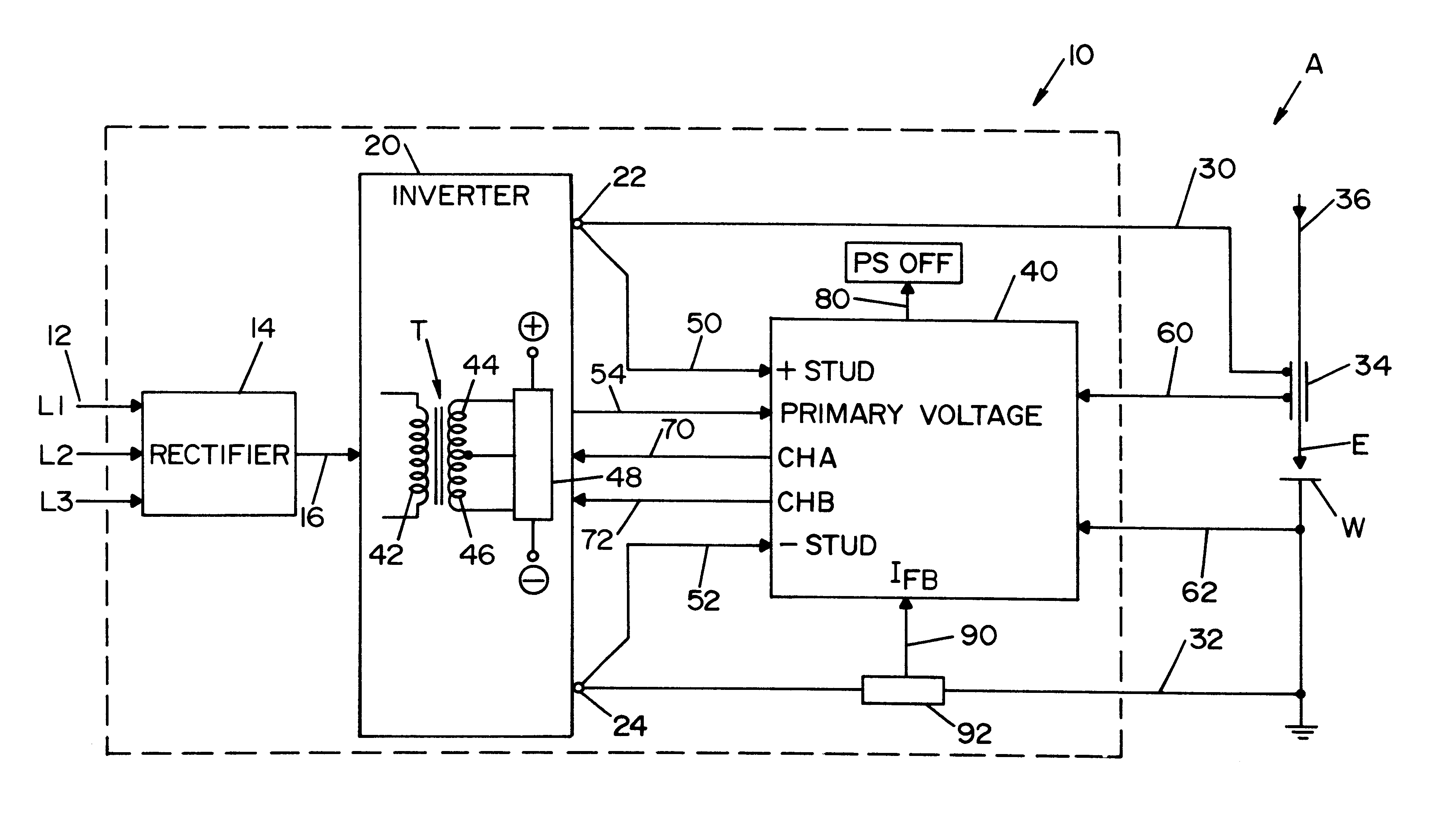
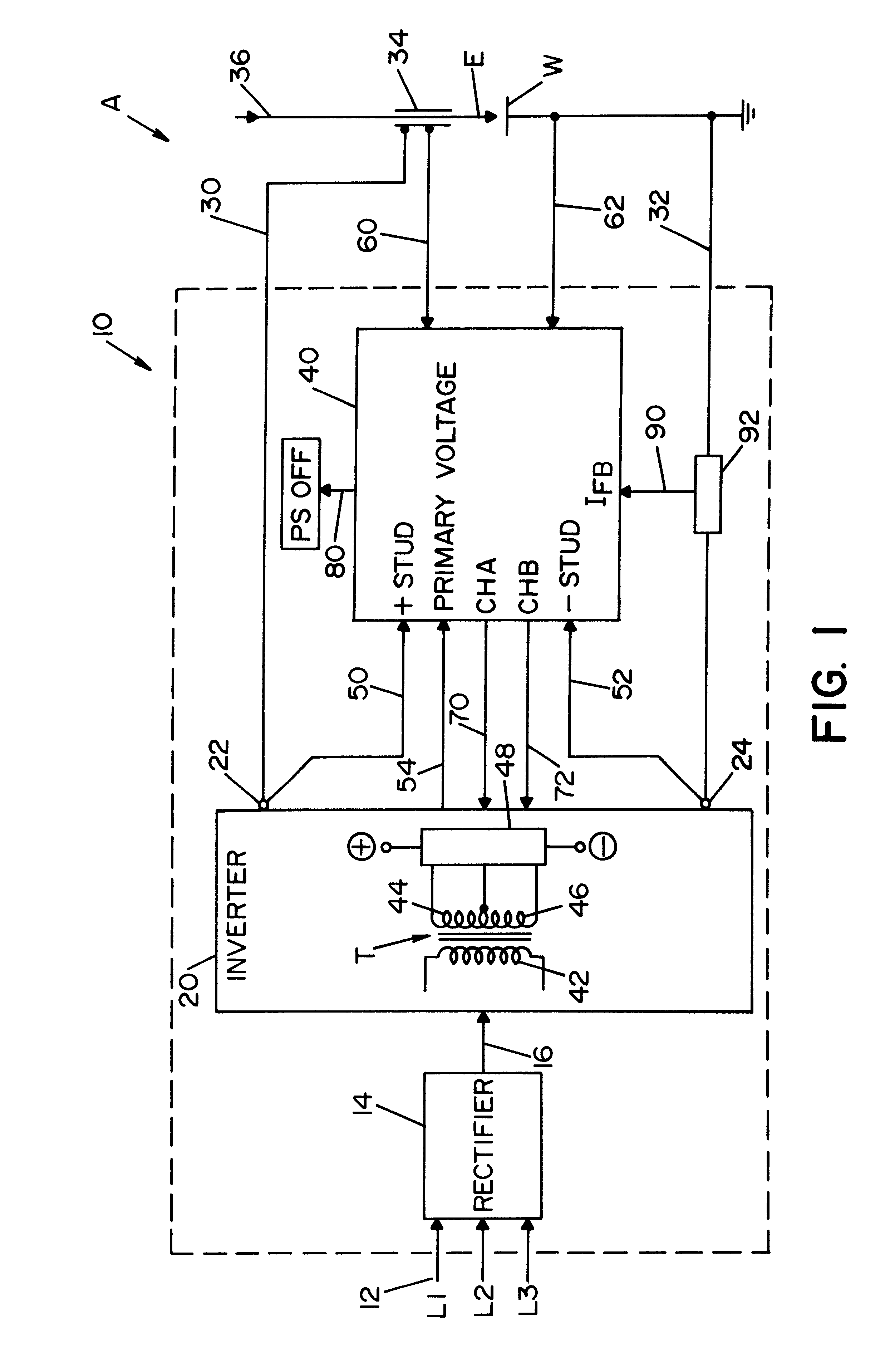
Referring now to the drawings, the showings are for the purpose of illustrating a preferred embodiment of the present invention, except for the prior art shown in FIG. 6. In FIG. 1, welder A includes a standard power source 10 shown in dashed lines. The power source is illustrated as a high switching speed inverter, such as the Power Wave manufactured by The Lincoln Electric Company. In the illustrated power source, a three phase power supply 12 is directed to a rectifier 14 to produce a DC link in line 16, which link is directed to the input of inverter 20 controlled by an internal controller having a digital signal processor to create a series of pulses determined by the duty cycle of a pulse width modulator. The pulse wave modulator controlled by a waveform generator or wave shaper in accordance with standard welding technology. The power source includes output studs 22, 24 connected to long weld cables 30, 32 electrically joining the studs with electrode E and work piece W. In a...


PUM

PropertyMeasurementUnit
Fractionaaaaaaaaaa
Fractionaaaaaaaaaa
Timeaaaaaaaaaa

Abstract

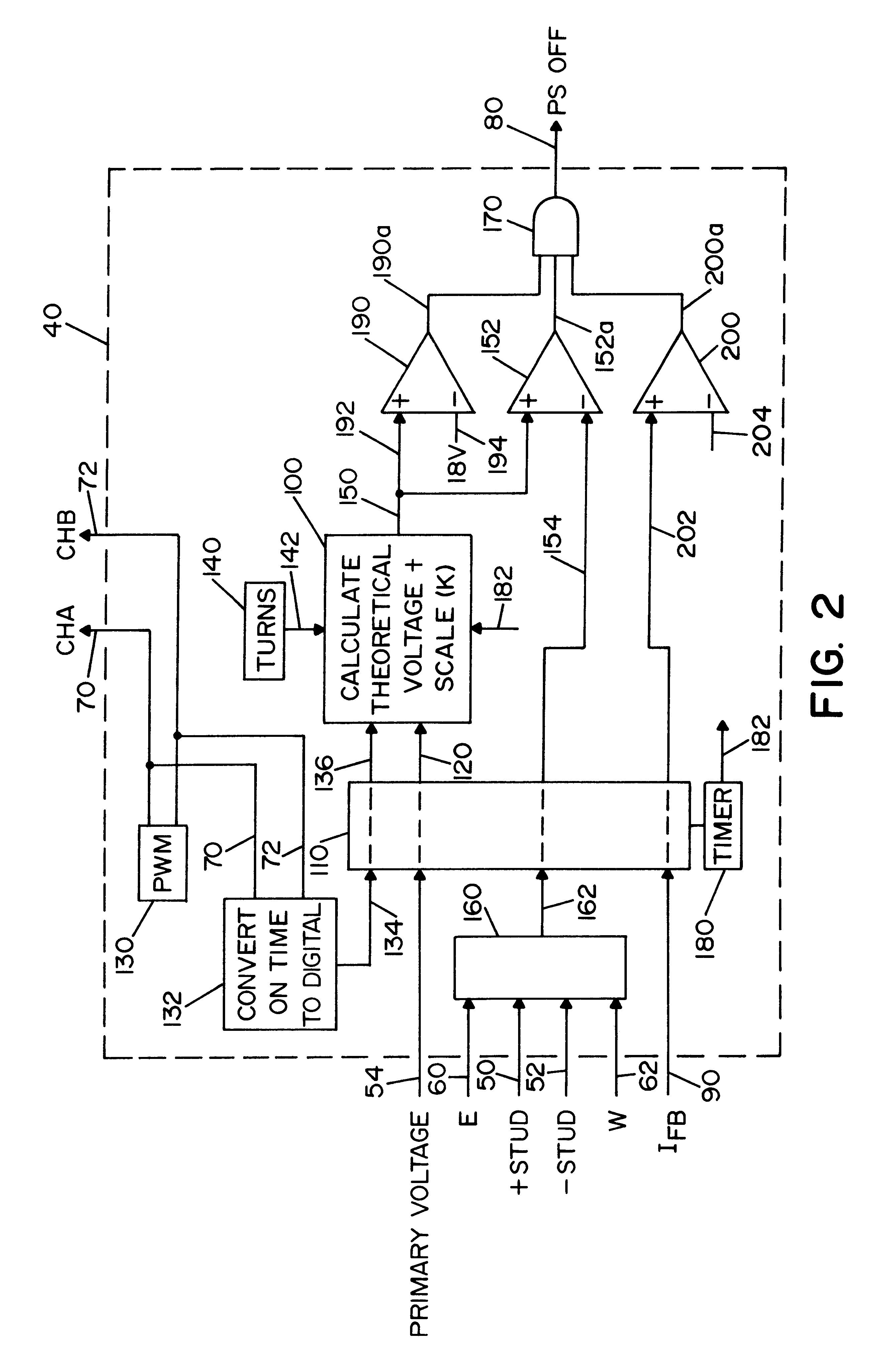
A device for terminating operation of the power source of an electric arc welder for passing a current between an electrode and work piece from a first stud connected to the electrode by a first cable and a second stud connected to the work piece by a second cable to perform a welding process. The welder includes an output transformer with a known turns ratio, a primary winding and secondary winding. A first voltage sense lead is connected to the electrode and a second voltage sense lead connected to the work piece. The novel device comprises an executive program to implement a test sequence involving (a) a program routine for comparing a real time theoretical voltage, determined by the pulse waveform at a given time of the waveform, and the voltage at the sense leads at the given time; (b) a program routine to terminate operation of the power source when the theoretical voltage substantially exceeds the sense lead voltage; and, (c) a timing routine to perform the executive program at a set period.

Description

This invention relates to the art of electric arc welding and more particularly to a device for monitoring the voltage sense leads of the power source during a welding operation. In addition, the invention involves the novel method of monitoring the continuity of the voltage leads using the unique monitoring device.BACKGROUND OF INVENTIONIn the electric arc welding technology, a power source passes a current between an electrode and a work piece. Often, the electrode is a continuous welding wire drawn from a supply of welding wire, such as a drum or reel, and passed through a contact tip on its way to being melted and deposited onto the work piece. In this type of welding procedure, the power source of the welder includes a first stud connected to the electrode, usually through the contact tip, and a second stud connected to the work piece Connections are by welding cables, which cables may be quite long and include a variety of impedance variables, such as inductive reactance based...

Claims


Application Information

Patent Timeline
IPC IPC(8): B23K9/10B23K9/095
CPCB23K9/1006B23K9/0953
Inventor KOOKEN, TODD E.MYERS, RUSSELL K.
Owner LINCOLN GLOBAL INC
Learn More