
Device, method, and storage medium for exponentiation and elliptic curve exponentiation

a technology of elliptic curve and exponentiation method, which is applied in the field of exponentiation techniques and elliptic curve exponentiation techniques, can solve the problems of poor performance of the improved signed binary method for a specific bit pattern, large amount of computation needed in the binary method, and large storage cost of storing an exponent in signed binary representation

Inactive Publication Date: 2003-05-20
PANASONIC CORP
View PDF9 Cites 34 Cited by
  • Summary
  • Abstract
  • Description
  • Claims
  • Application Information

AI Technical Summary

Benefits of technology

is to provide an exponentiation device that can limit the number of multiplications in exponentiation to approximately that of the signed binary method on average and to that of the original binary method in the worst case, while maintaining the size of the exponent storage close to that of the original binary method.
The third object of the invention is to provide an exponentiation method for use in an exponentiation device, that can reduce the size of the exponent storage and the number of multiplications.
The modular exponentiation device of the fourth object and the elliptic curve exponentiation device of the fifth object have constructions same as or analogous to the exponentiation device. Accordingly, like the exponentiation device, the modular exponentiation device and the elliptic curve exponentiation device can reduce the number of multiplications needed, without having to significantly increase the size of the exponent storage.

Problems solved by technology

Thus, a large amount of computation is needed in the binary method.
However, storing an exponent in signed binary representation costs a storage at least twice as large as that of the binary method.
Nevertheless, the performance of the improved signed binary method is poor for a specific bit pattern, such as 0010, of an exponent.

Method used


Image

  • Device, method, and storage medium for exponentiation and elliptic curve exponentiation
  • Device, method, and storage medium for exponentiation and elliptic curve exponentiation
  • Device, method, and storage medium for exponentiation and elliptic curve exponentiation

Examples


Embodiment Construction

)

The following is a description of an embodiment of the present invention with reference to the figures.

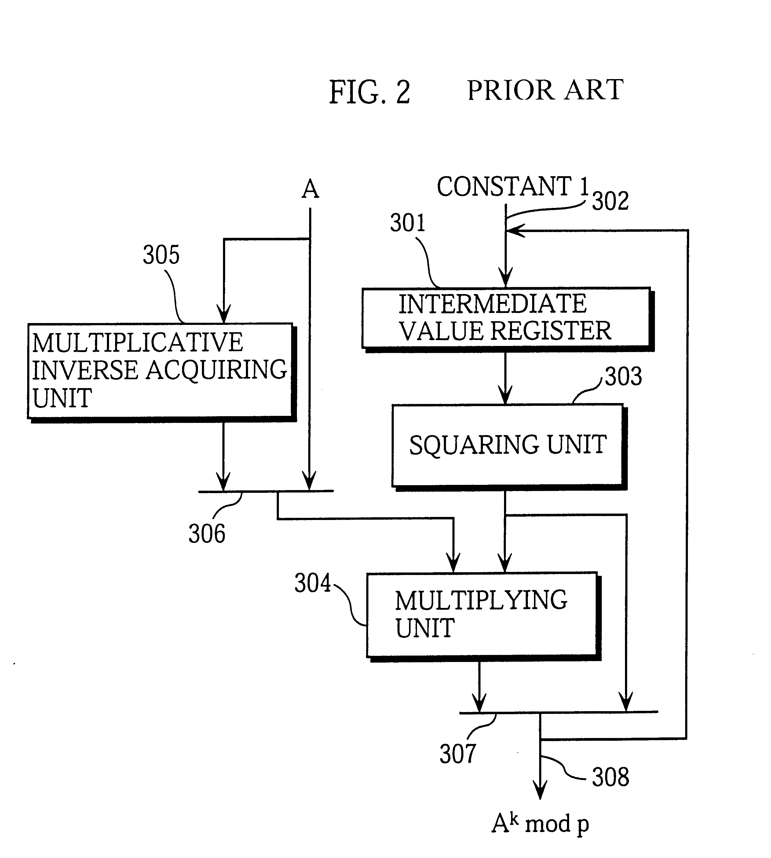
A modular exponentiation device according to the embodiment of the invention has the construction shown in FIG. 4. In this modular exponentiation device, an exponent processing unit 101 processes an exponent k (in binary representation) and outputs the processed exponent to an operating unit 106, and the operating unit 106 exponentiates a base A by the processed exponent modulo a prime p, thereby obtaining A.sup.k mod p.

FIG. 1 shows the detailed construction of the exponent processing unit 101 that constitutes the difference with the prior art techniques.

In the figure, a holding register 201 has a storage of n+2 bits, n being the bit length of the exponent k. The reason why 2 has been added to the exponent's bit length n is that one bit will be used as a sign bit and the other bit will be needed as a result of the exponent k being transformed into a signed binary representation. T...


PUM


Abstract

An exponent preprocessing unit preprocesses an n-bit exponent k and exponentiates a base A by the preprocessed exponent k. A bit string storing unit stores a bit string including a sign bit and the exponent k. A reading unit reads a bit pattern composed of the sign bit and a bit sequence made up of a predetermined number of bits. A bit pattern generating unit generates a new bit pattern from the read bit pattern. An operation pattern specifying unit specifies an operation pattern based on the read bit pattern. An operating unit performs an operation according to the specified operation pattern and writes the new bit pattern over the previous bit pattern. The reading unit reads a next bit sequence starting from a different bit in the bit string storing unit. A repeat controlling unit repeats these procedures n+1 times.

Description

This application is based on an application No. H11-069104 filed in Japan, the content of which is hereby incorporated by reference.1. Field of the InventionThe present invention relates to exponentiation techniques and elliptic curve exponentiation techniques for use in areas such as cryptography.2. Description of the Prior ArtCryptographic communications allow specific terminals to securely communicate with each other in a network coupled to a plurality of terminals. One of cryptographic systems used for such cryptographic communications is the so-called public key cryptosystem. Examples of public key cryptosystems are the RSA (Rivest-Shamir-Adelman) and ElGamal systems. These public key cryptosystems perform exponentiation in encryption or decryption processing, in such a way as to exponentiate a message by an encryption key or exponentiate a ciphertext by a decryption key.Another type of public key cryptosystems is a cryptosystem that uses elliptic curves. While other public key...

Claims


Application Information

Patent Timeline
IPC IPC(8): G06F7/72G06F7/60
CPCG06F7/723G06F7/725G06F2207/7285
Inventor ONO, TAKATOSHIMATSUZAKI, NATSUME
Owner PANASONIC CORP
Learn More