
Safety electrical outlet with logic control circuit

a logic control circuit and electrical outlet technology, applied in the direction of relays, emergency protective arrangements for limiting excess voltage/current, coupling device connections, etc., can solve the problems of power loss, overheating and potential fire, and thousands of people being killed or injured

Inactive Publication Date: 2003-04-22
BLACKBIRD TECH
View PDF11 Cites 133 Cited by
  • Summary
  • Abstract
  • Description
  • Claims
  • Application Information

AI Technical Summary

Problems solved by technology

Every year thousands of people are killed or injured by accidents and fires caused by faulty electrical devices or appliances causing electrical shock.
The logic circuit will sense this condition and the power will remain off, i.e., the smart outlet will not provide any power to the device or appliance.
If the electrical circuit is interrupted or overloaded, a fault is detected and the logic circuit of the smart outlet shuts the power to the connected device or appliance off.
This feature addresses the problems of overloading outlets with too many appliances or devices, which causes overheating and potential fire.
Overheating is often caused by a defective plug, that is, a plug which is either physically damaged, rusty, or corroded.
This high resistance causes a power loss and will raise the temperature of the outlet structure.
Ultimately, the combustion temperature of the wall material or the insulation on the wiring may be reached, and a fire will occur.

Method used


Image

  • Safety electrical outlet with logic control circuit
  • Safety electrical outlet with logic control circuit
  • Safety electrical outlet with logic control circuit

Examples


Embodiment Construction

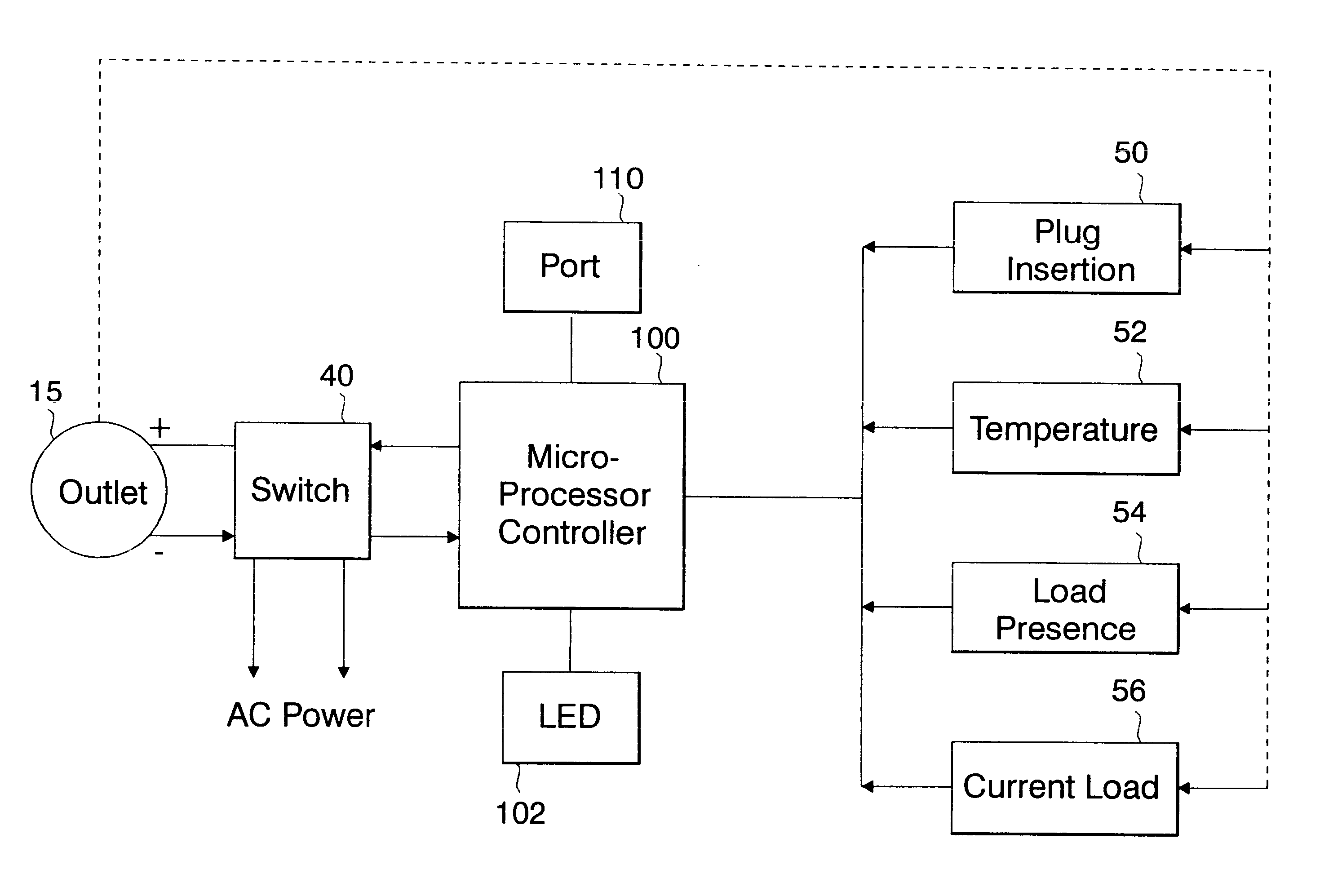
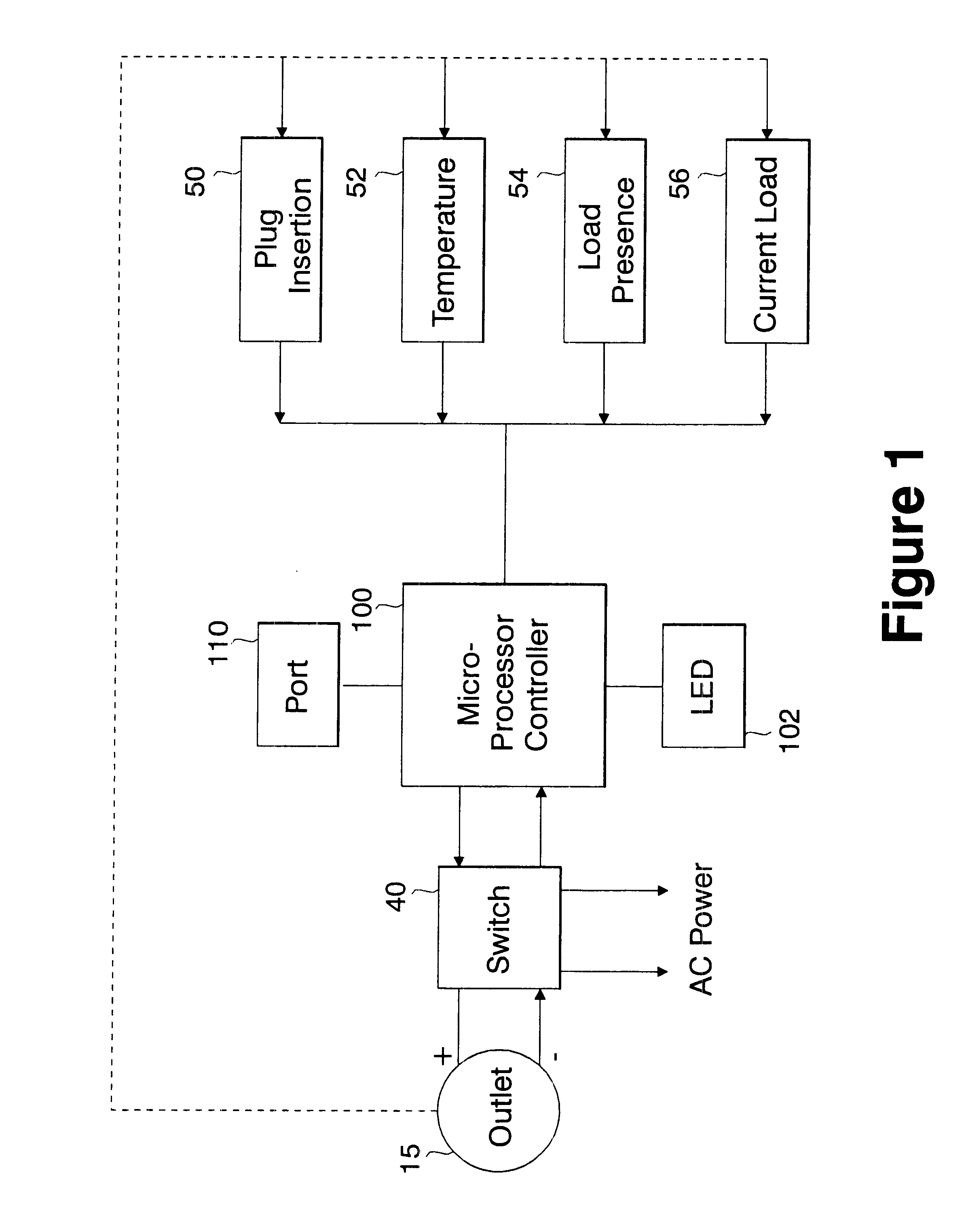
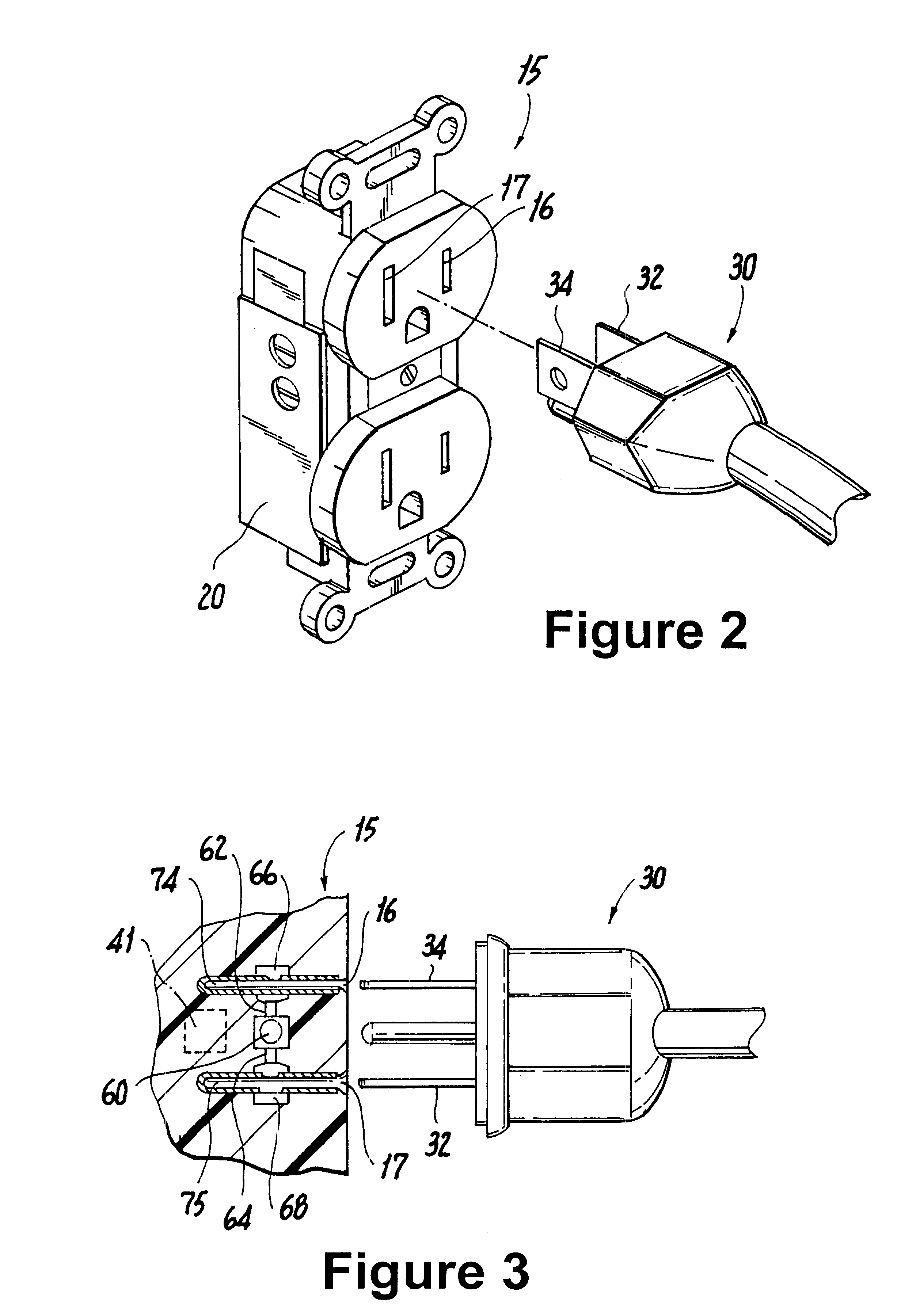
FIG. 1 illustrates an overall block diagram of the invention. The wall outlet 15 represents a standard wall mounted outlet and may be a dual outlet, as shown in FIG. 2. The outlet may include all functions of a ground fault interrupter, as is known in the prior art and which is not further described here. Physically associated with the wall outlet 15 is a board 20, for example a PCB board containing the circuitry for monitoring at least four conditions that need to conform in order for the outlet to provide power to any connected device or apparatus. The four monitored functions are proper plug insertion 50; load presence monitoring 54 and current load monitoring 56, as well as temperature sensing 52 in the outlet. Signals inputs from these four sensing or monitoring circuits are analyzed by the micro processor 100 which in turn triggers an electrically controlled switch 40, such as a relay, to provide or not provide power to the outlet 15. The inputs of signals from these four sens...


PUM


Abstract

An electrical safety outlet for accepting a plug to provide power to electrical appliances including a power supply and an intelligent circuitry for controlling the power supply to the electrical outlet; the intelligent circuitry includes circuits for determining temperature condition in the outlet, mechanical plug insertion into the outlet, load presence on the outlet, and current capacity conditions.

Description

1. Field of the InventionThe present invention relates to a logic control device that can be integrated into any double or single household or commercial electrical outlet. It controls the outlet and transforms it into a safe and "smart" outlet. The device can also be integrated into an extension cord, adapter or placed over an outlet as a cover plate. The logic circuit in the smart outlet instantly senses the state and condition of itself and the physical and electrical changes that occur.2. Description of the Related ArtEvery year thousands of people are killed or injured by accidents and fires caused by faulty electrical devices or appliances causing electrical shock. Many protective devices are being implemented to protect young children from accidentally accessing an electrical outlet, causing injuries due to electrical shock. Modern appliances that are more prone to cause accidents are equipped with ground fault protection. Such ground fault circuitry interrupters either inter...

Claims


Application Information

Patent Timeline
Patent Type & Authority Patents(United States)
IPC IPC(8): H02H3/12H01R13/70H01R13/713H02H5/04H02H5/00
CPCH01R13/713H02H3/12H01R13/652H02H5/042H01R2103/00H01R24/78
Inventor WEINBERGER, PEDRO J.
Owner BLACKBIRD TECH
Learn More