
Pump for molten materials with suspended solids

a technology of suspended solids and molten materials, which is applied in the direction of liquid fuel engines, marine propulsion, vessel construction, etc., can solve the problems of difficult to maintain a connection between metallic and graphite components, mechanical stress on components, and not the most advantageous material to be used for complicated shapes and mechanical stress,

Inactive Publication Date: 2003-04-22
PYROTECK INC +1
View PDF6 Cites 104 Cited by
  • Summary
  • Abstract
  • Description
  • Claims
  • Application Information

AI Technical Summary

Benefits of technology

Another advantage of the present invention is the provision of an impeller having grooves machined into its peripheral surface which enhances the sealing characteristics of a pump assembly.
Another advantage of the present invention is the provision of a deflector plate which weighs on and enhances the sealing characteristics of the pump sealing assembly.
Yet another advantage of the present invention resides in the ability of the molten material pump to maintain effective operation and alignment after thermal expansion of the rotating shaft has occurred.
Still another advantage of the present invention resides in the ability of the molten material pump to maintain proper alignment upon bending or movement of the support riser during operation.

Problems solved by technology

Although pumps of the foregoing type have been in effective operation for several years, they still suffer from a variety of shortcomings.
Although graphite has advantages when used for certain components of molten material pumps, it is not the most advantageous material to be used for complicated shapes and mechanically stressed components.
The problem with using these materials is that the base member and impeller are typically constructed from graphite (due to its wear characteristics) and it is difficult to maintain a connection between metallic and graphite components.
Such a difficulty arises because of the differences in thermal expansion experienced by these materials.
Accordingly, bolts and conventional fasteners are generally not feasible connecting mechanisms.
A second problem arises in connection with attaching a metallic shaft to a graphite impeller.
Even when the two components to be connected are of the same material, such as the base and riser of a pump for processing molten zinc or molten magnesium, there are connection problems.
For example, the use of bolts and fasteners as a connecting mechanism do not provide optimal strength.
A third problem with known molten material pumps is that the pump components are often manufactured with clearances, tolerances, etc. which permit molten materials to escape from the cavity or housing of the base member.
Accordingly it is difficult to maintain an effective seal within the base member's housing.
A fourth problem associated with the foregoing molten material pumps is that the shafts of these pumps have a tendency to grow in length at elevated temperatures due to thermal expansion.
The increased length often pushes the pump out of alignment.

Method used


Image

  • Pump for molten materials with suspended solids
  • Pump for molten materials with suspended solids
  • Pump for molten materials with suspended solids

Examples


Embodiment Construction

Reference will now be made in detail to the present preferred embodiments of the invention, examples of which are illustrated in the accompanying drawings. While the invention will be described in connection with the preferred embodiments, it will be understood that it is not intended to limit the invention to those embodiments. On the contrary, it is intended to cover all alternatives, modifications and equivalents that may be included within the spirit and scope of the invention defined by the appended claims.

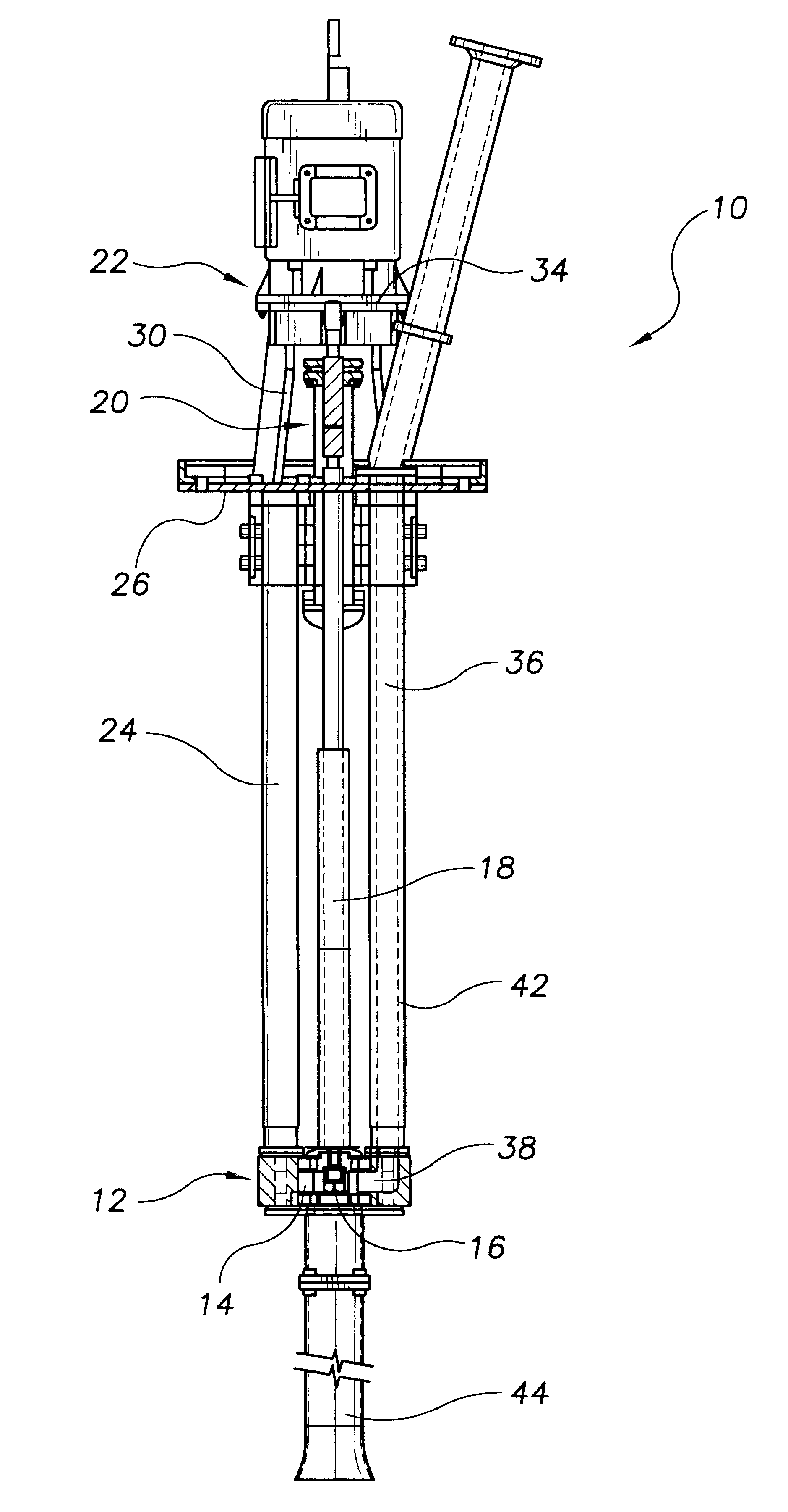
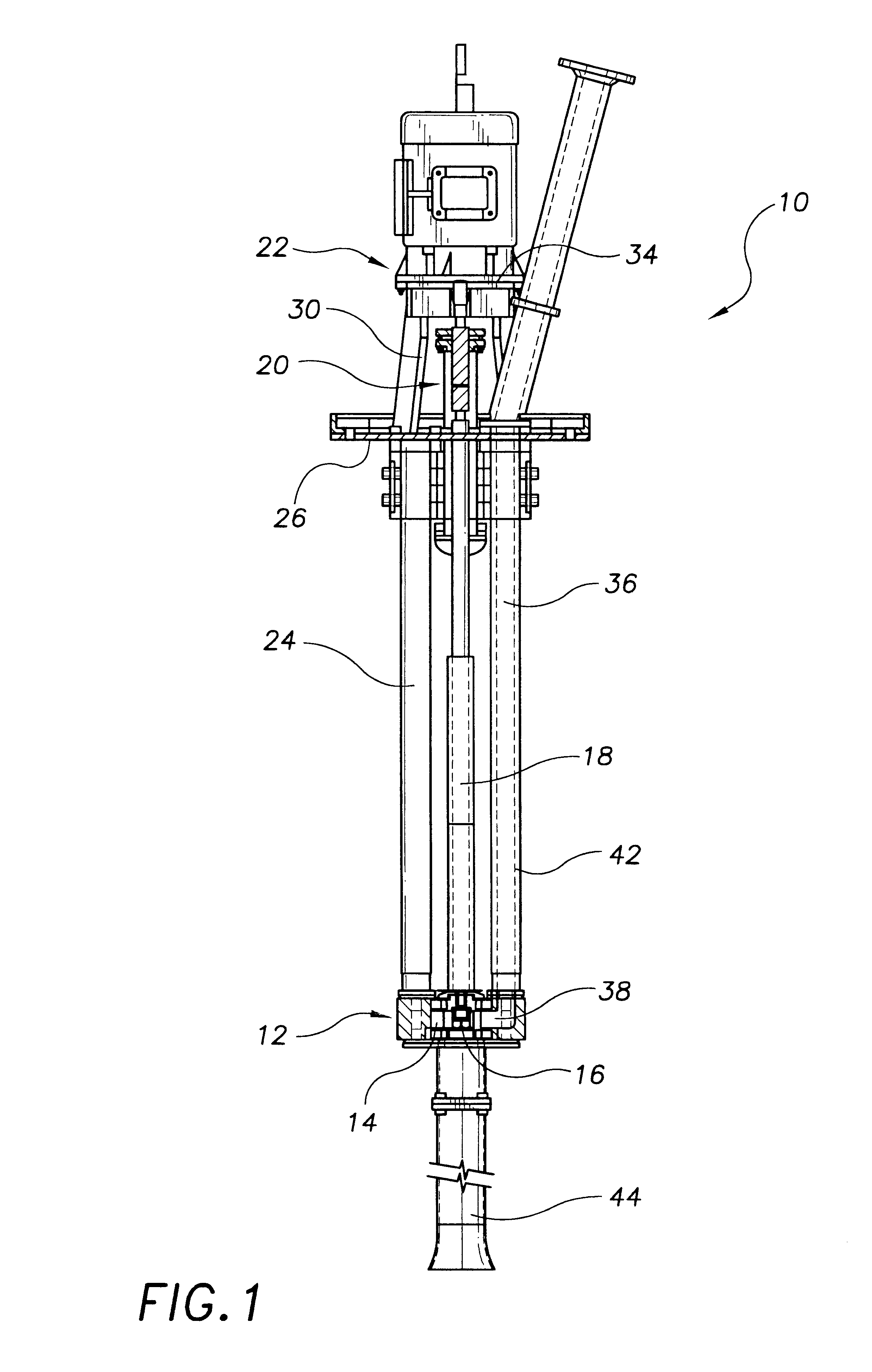
Referring now to FIG. 1, a typical molten material pump is indicated generally by the reference numeral 10. The pump is adapted to be immersed in a molten material contained within a vessel (not shown). The vessel can be any container holding a molten material. Although a transfer pump is depicted, it should be understood that the pump can be any type of pump suitable for pumping molten materials, such as a circulation pump or gas injection pump. Generally, however, the pump ...


PUM


Abstract

A molten material pump includes an impeller housed within a base member of the pump. A plurality of grooves are defined in a peripheral sidewall of the impeller for either drawing a molten material into the base member's chamber or pushing molten material out of the base member's chamber. The impeller is rotated by a rotatable shaft connected to an upper surface of the impeller. The rotatable shaft includes a non-circular shaped lower end dimensioned to be received within a cooperating opening in the impeller. The molten material pump further includes a connecting assembly for interconnecting components of the molten material pump. The connecting assembly includes a first mounting member attached to a first pump component that is dimensioned to be fitted within a cooperating recess of a second mounting member attached to a second pump component. In another embodiment of the invention, a stub shaft connects an upper shaft portion of the shaft to the impeller. The stub shaft includes a universal joint that is not rigidly connected to the upper shaft portion. In addition, the universal shaft is configured to allow the stub shaft and impeller to pivot. A floating deflector block weighs on an upper sealing block of the pump for enhancing the seal at the pump's bearing surfaces.

Description

1. Field of the InventionThis invention relates generally to the art of processing and treating molten metal, molten alloys, molten salts, or any other molten materials (hereinafter collectively referred to as "molten materials").2. Discussion of the ArtIn the course of processing molten materials, it is often necessary to transfer the molten materials from one vessel to another or to circulate the molten materials within a vessel. Pumps for processing molten materials are commonly used for these purposes. The pumps can also be used for other purposes, such as to inject purifying gases into the molten materials being pumped. A variety of pumps as described are available from Metaullics Systems Co., L.P., 31935 Aurora Road, Solon, Ohio 44139.In the case where a molten material is melted in a reverbatory furnace, the furnace is typically provided with an external well in which a pump is disposed. When it is desired to remove molten materials from the vessel, a transfer pump is used. W...

Claims


Application Information

Patent Timeline
Patent Type & Authority Patents(United States)
IPC IPC(8): F04D7/00F04D7/04F04D7/06F04D29/22
CPCF04D7/065F04D7/045
Inventor MORDUE, GEORGE S.BRIGHT, MARK A.
Owner PYROTECK INC
Learn More