
Method of applying a slider to a fastener-carrying plastic web

Inactive Publication Date: 2003-03-04
REYNOLDS PRESTO PRODS
View PDF138 Cites 74 Cited by
  • Summary
  • Abstract
  • Description
  • Claims
  • Application Information

AI Technical Summary

Benefits of technology

Accordingly, an object of the present invention is to provide a method of applying a slider to a fastener-carrying web of plastic film that allows the fastener to be easily accessed and controlled for installing the slider and performing other fastener-related operations after the fastener is attached to the web.
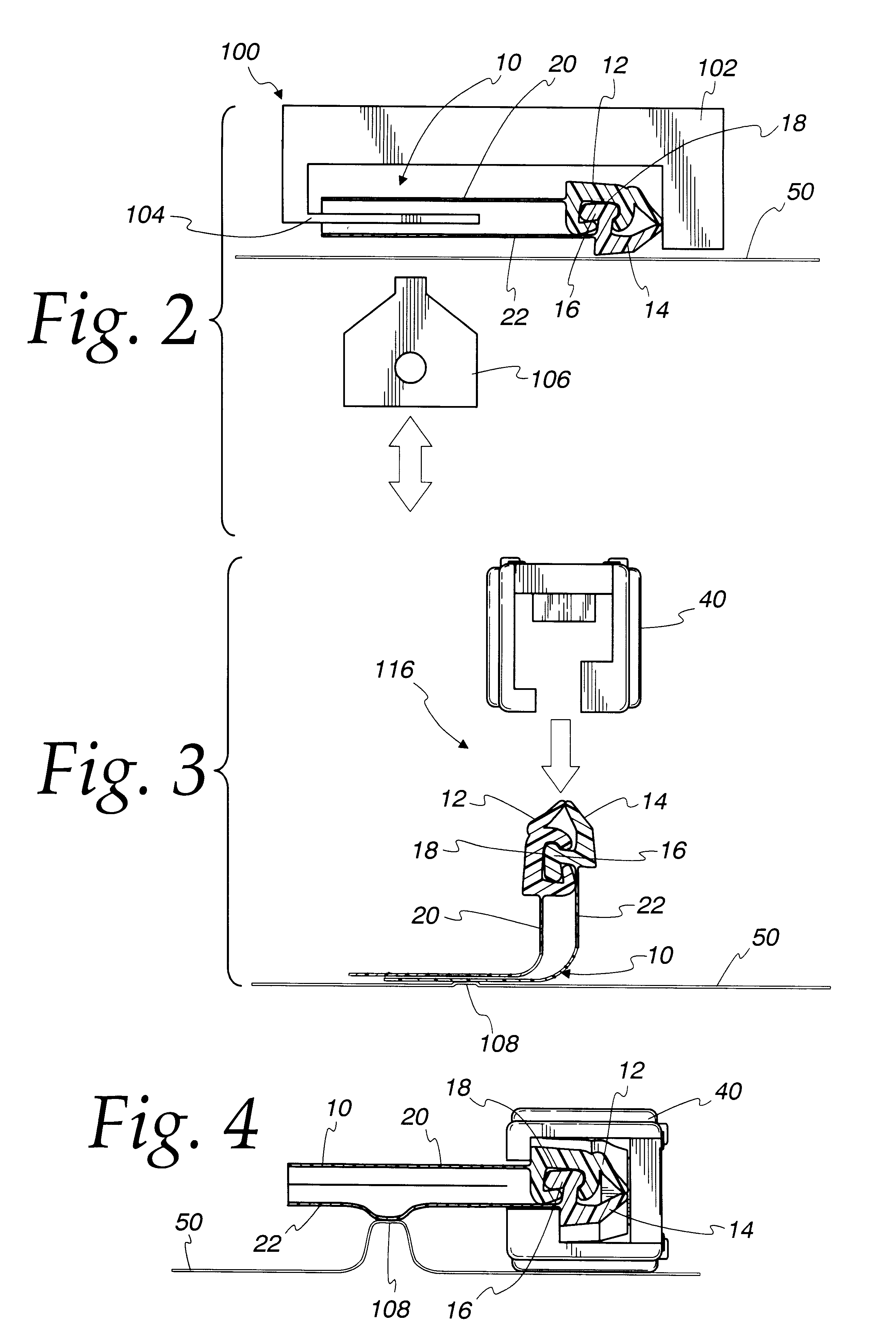
This and other objects are realized by the following method of applying a slider to a fastener-carrying web of plastic film. The fastener includes interlockable profiles and fins depending from the respective profiles. One of the fins is attached to the web of plastic film such that the profiles are immediately adjacent to the web. The fastener is folded away from the web about the attached fin such that the profiles and proximate portions of the fins are oriented at an angle, preferably about 90 degrees, relative the web. Because the profiles and proximate fin portions are oriented at an angle relative to the web, they can be easily accessed and controlled for applying the slider to the profiles and performing other fastener-related operations.

Problems solved by technology

Unless sliders are applied to the fastener prior to attaching the fastener to the moving web, it is difficult to access and control the fastener for installing sliders and performing other fastener-related operations after the fastener is attached near the center of the moving web.
Because the fastener is parallel and close to the same plane as the web, gaining access to the fastener for applying sliders becomes limited by the close proximity of the fastener to the web.

Method used


Image

  • Method of applying a slider to a fastener-carrying plastic web
  • Method of applying a slider to a fastener-carrying plastic web
  • Method of applying a slider to a fastener-carrying plastic web

Examples


Embodiment Construction

Turning to the drawings, FIG. 1 depicts a method of making a slider-operated fastener for use in reclosable plastic bags. In the method, there is provided a continuous fastener 10 including first and second opposing tracks 12 and 14. The tracks 12 and 14 include respective first and second interlocking profiles 16 and 18 and respective first and second fins 20 and 22 extending downward from the respective profiles 16 and 18. The profile 16 preferably includes a rib, and the profile 18 preferably includes a groove for receiving the rib. Further details concerning the construction of the profiles 16 and 18 may be obtained from U.S. Pat. No. 5,007,143 to Herrington, which is incorporated herein by reference in its entirety. The fastener 10 may be unwound from a spool or the like.

The fastener 10 is conveyed along a web of plastic film 50 to a fin seal station 100 (FIGS. 1 and 2). The fin seal station 100 includes a guide 102 with a splitter 104 that extends between the fins 20 and 22. T...


PUM

PropertyMeasurementUnit
Angleaaaaaaaaaa
Angleaaaaaaaaaa
Plasticityaaaaaaaaaa

Abstract

A method of applying a slider to a fastener-carrying web of plastic film. The fastener includes interlockable profiles and fins depending from the respective profiles. One of the fins is attached to the web of plastic film such that the profiles are immediately adjacent to the web. The fastener is folded away from the web about the attached fin such that the profiles and proximate portions of the fins are oriented at an angle, preferably about 90 degrees, relative the web. Because the profiles and proximate fin portions are oriented at an angle relative to the web, they can be easily accessed and controlled for applying the slider to the profiles and performing other fastener-related operations.

Description

FIELD OF THE INVENTIONThe present invention generally relates to reclosable plastic bags and, more particularly, to a method of applying a slider to a fastener-carrying web of plastic film.BACKGROUND OF THE INVENTIONIn one method of making slider-operated reclosable plastic bags, a continuous fastener is sealed to opposing longitudinal edges of a folded web of thermoplastic film moving in a longitudinal direction. To form individual bags, the folded web is sealed at bag-width distances apart along side seals that are generally transverse to the direction of web movement. To facilitate opening and closing the fastener, sliders are applied to the fastener at bag-width distances apart either just before or just after the side seals are formed in the folded web. In another method of making slider-operated reclosable plastic bags, the sliders are applied to the fastener prior to attaching the fastener to the moving web. In each of the above-noted methods, the fastener is positioned relat...

Claims


Application Information

Patent Timeline
IPC IPC(8): B31B19/00B31B19/90B65B61/18
CPCB31B19/90B65B61/188B31B2219/9019Y10T29/533Y10S493/927B31B70/8132
Inventor STRAND, AARON L.PROVAN, ALEXANDER R.COOMBER, THOMAS L.THOMAS, TOBY R.
Owner REYNOLDS PRESTO PRODS
Learn More