
Birdcage torsion harness assembly for rotating gimbal

a technology of torsion harness and rotating gimbal, which is applied in the direction of electrical/fluid circuit, vehicle components, electrical apparatus, etc., can solve the problems of generating both torsion and bending stress, the packaging of conventional torsion-loop designed harnesses usually does not allow axial displacement, and the moment that multiplies the restrictive for

Inactive Publication Date: 2003-01-28
RAYTHEON CO
View PDF11 Cites 2 Cited by
  • Summary
  • Abstract
  • Description
  • Claims
  • Application Information

AI Technical Summary

Benefits of technology

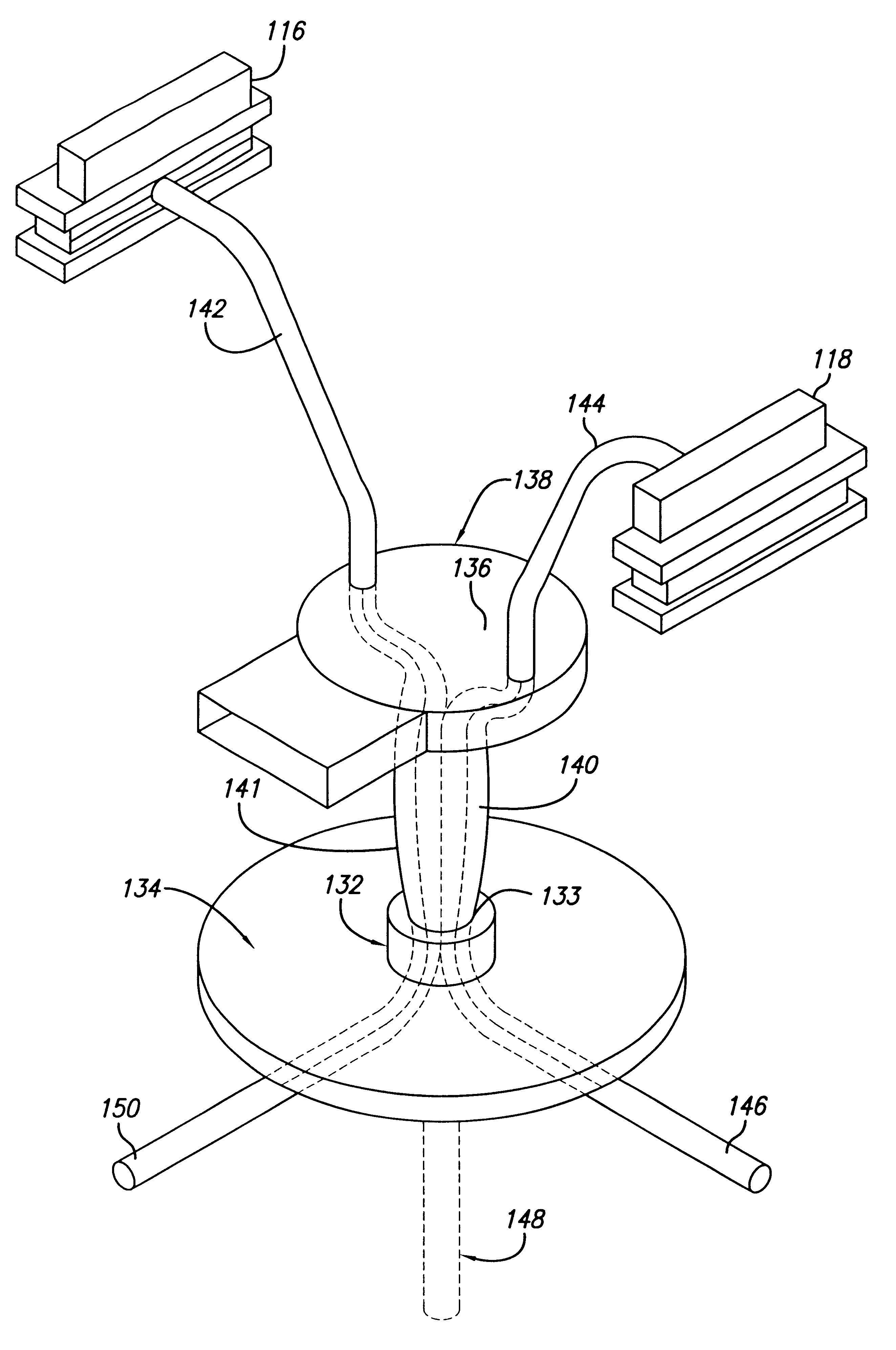
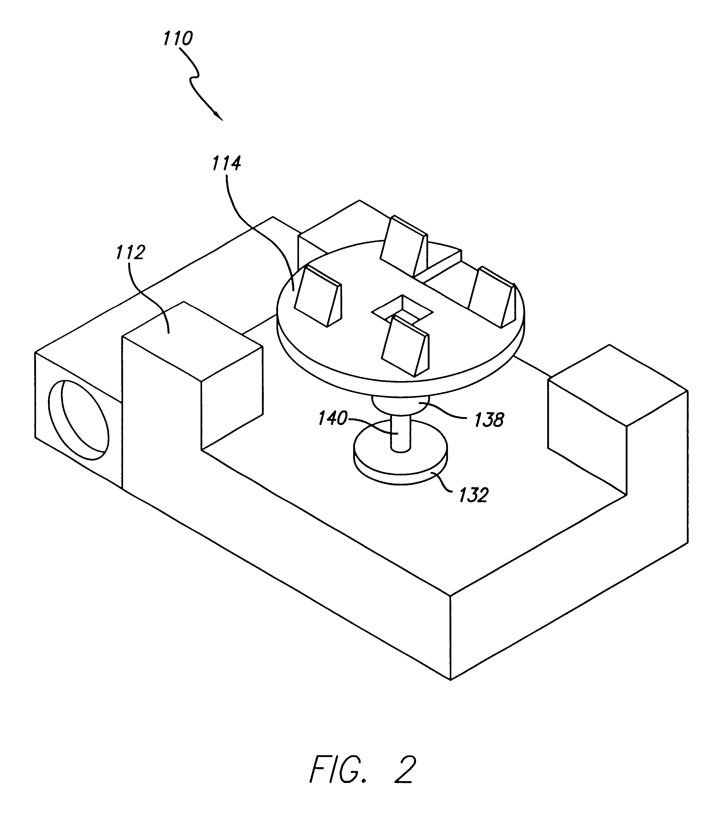
The lower potting block is mounted on the bulkhead or sensor support at a set distance from the upper potting block carefully determined such that the plurality of conductor strands extending from the gimbal to the bulkhead form a substantially bird cage configuration. In particular, the bundle of conductor strands are each bowed in a generally outwardly direction from the axis of the bundle which coincides with the axis of rotation of the gimbal member. The predetermined amount of "birdcaging" or bowing of the various individual conductor strands may easily be controlled by controlling the axial separation of the lower and upper potting blocks.
At first inspection, the birdcage-shaped torsion harness of the present invention appears to move or navigate with the gimbal in pure torsion. While it is true that the bowed conductors do twist as the gimbal moves though an angle of rotation, it becomes clear that the individual conductor strands primarily move in bending. Because the individual strands are pre-compressed into their initial bowed or birdcage-shaped positions, movement of the gimbal has the effect of providing slack that is taken up in the strands as the gimbal rotates relative to the fixed position sensor. In effect, the conductor strands bend or stretch from their respective bowed configurations until they reach substantially linear shape. The conductor strands then bend back into their original bowed shapes as the gimbal rotates back to its original neutral position.
An advantage of the present invention resides in the effective reduction of the size of the harness package as compared to conventional loop harnesses. In particular, loop harnesses extending between the support and gimbal are required to be substantially longer than the preferred approximate one (1) inch length of the birdcage conductors. The loop conductors must be longer because they require a relatively large "swing" or range of motion per angle of rotation of the gimbal. Besides reducing the package size of the harness assembly, the birdcage design eliminates the high stress normally inherent in harness assemblies facing large angles of rotation of the gimbal. In addition, the birdcage harness is not G sensitive, and dramatically reduces spring torque and friction input to gimbaled system components caused by conventional loop harness assemblies.

Problems solved by technology

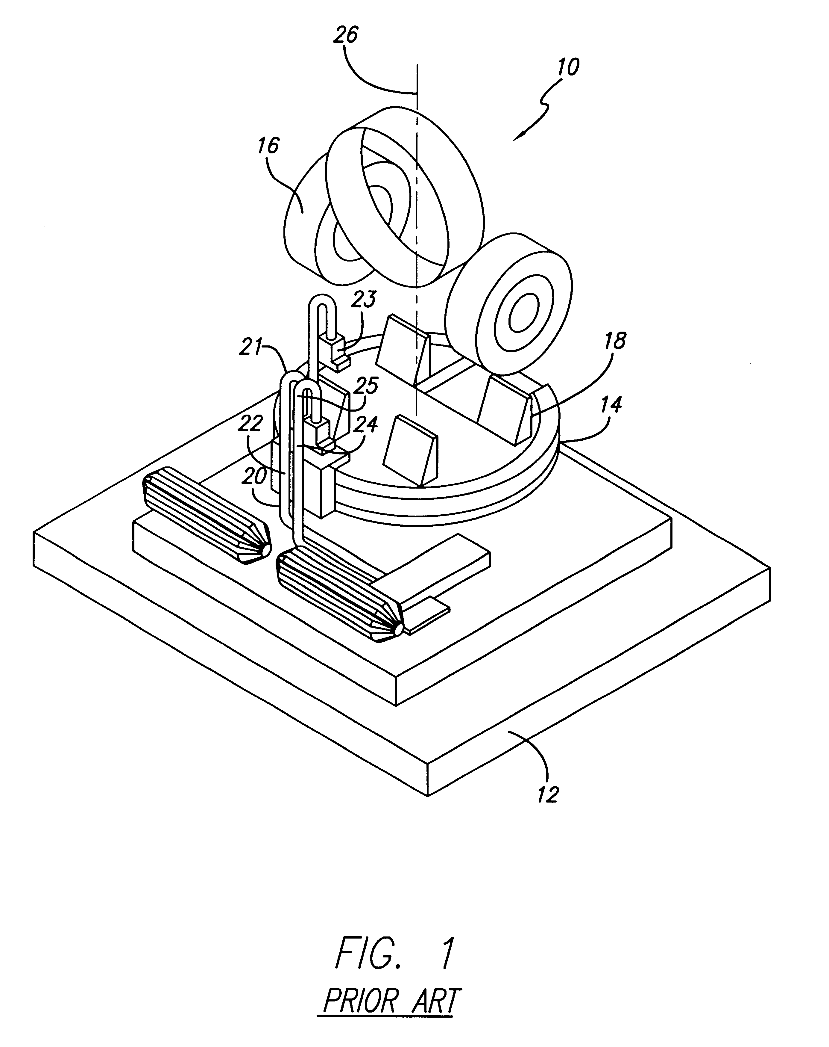
These designs exercise, stretch, bend or twist the conductors, resulting in the generation of both torsion and bending stress.
However, the packaging for conventional torsion-loop designed harnesses usually does not allow for axial displacement.
This can result in a moment that multiplies the restrictive force caused by the harness.
As a result, the performance of conventional torsion-loop harnesses tends to degrade sharply with the addition of each conductor and shield added to the bundle.
When least offensive, EMI still can serve to reduce the effectiveness of any electromechanical assembly.
EMI can render such an assembly useless.
Another drawback of conventional harness systems resides in the fact that such systems function as miniature antennas by intercepting and introducing electro-magnetic waves into the assembly.
However, the problem can not be solved so easily when the harness is dynamic as with cross-gimbal systems.
Torsion-loop harnesses also tend to be very sensitive to G force inputs.
When employed in a missile seeker assembly and the entire seeker is put under heavy G forces as occur during flight, the loop harness assembles are susceptible to "flopping " around and possibly interfering with one another or with the gimbal components.
In addition, because torsion-loop harnesses require tight bend radii, the conductor strands and shielding may undergo some plastic deformation which, in turn, increases the force required to overcome or extend the harness.
In addition, over time the metal material in the bundle of conductors begins to "creep" or cold flow at the location of the tight bend radius.
This is undesirable in closed loop control systems.
In effect, material work hardening and material creep adversely effect the performance of the loop harness over cycle time.
In addition, the birdcage harness is not G sensitive, and dramatically reduces spring torque and friction input to gimbaled system components caused by conventional loop harness assemblies.

Method used


Image

  • Birdcage torsion harness assembly for rotating gimbal
  • Birdcage torsion harness assembly for rotating gimbal
  • Birdcage torsion harness assembly for rotating gimbal

Examples


Embodiment Construction

Illustrative embodiments and exemplary applications are described below with reference to the accompanying drawings in order to disclose the advantageous teachings of the present invention.

As will be explained below, the present invention is unique in its ability to reduce the EMI problem described above as compared with existing harness assembles by minimizing the movement of the wire forming the bundles. Known "twist cap" wire arrangements require relatively long wires and incorporate a geometry which requires the wires to fold and slide over one another as the gimbal navigates across a specified angle. This movement is quantified as D.congruent.2.pi.d(.O slashed. / 360), where d is the diameter of a twist cap and .O slashed. is the gimbal angle navigated. An average diameter for a twist cap housing including 30-40 conductors is about 2 inches. For a twist cap navigating 180 degrees D (movement of the wires) equates to about 6 inches. By comparison, the present invention employs con...


PUM


Abstract

A birdcage-shaped harness assembly adaptable for electrically connecting a bulkhead support structure with a rotatable gimbal support structure. In order to avoid excessive torsional forces from acting on the harness, a plurality of conductor portions are bundled together and pre-compressed in length between the support structures. When assembled, the conductor portions of the harness assembly form a birdcage-shaped dynamic bundle wherein the middle of the conductor portions bow away from conductor portions on the opposite side of the bundle. This pre-compression creates a birdcage-shaped configuration that allows the bundle to bend as the conductor portions straighten. This occurs when the gimbal rotates relative to the bulkhead. The bending motion creates relatively little damage to the conductor strands as compared the excessive torsion forces affecting conventional loop-shaped wire harness assemblies.

Description

1. Field of the InventionThe present invention relates to a harness assemblies. More specifically, the present invention relates to harness assemblies for rotating gimbals.2. Description of the Related ArtIn a gimbaled system, one or more gimbals are typically supported for movement relative to a stationary support member. In order to electrically connect components mounted on the gimbal with the stationary support member, a number of conductors are bundled together in what is conventionally referred to a harness assembly.Conventional harness assemblies often employ a torsion-loop design. These designs exercise, stretch, bend or twist the conductors, resulting in the generation of both torsion and bending stress. The tighter the bend radius and the larger the dynamic range, the greater the stress on the conductors when the harness cycles through its range of motion. To ensure proper movement of the gimbal and harness, the packaging of the harness loop is made relatively loose.Howeve...

Claims


Application Information

Patent Timeline
Patent Type & Authority Patents(United States)
IPC IPC(8): B60R16/02H01R35/02H01R35/00
CPCH01R35/025B60R16/0207
Inventor DUDEN, QUINTSEASLY, ZAC
Owner RAYTHEON CO
Learn More