
Method for dynamically allocating carriers in a wireless packet network, with reuse of carriers

a wireless packet network and carrier technology, applied in the field of packetized wireless communication networks, can solve the problems of a large trade-off between delay and efficiency of channel usage, relatively long delays, and more severe trade-offs

Inactive Publication Date: 2002-12-17
LUCENT TECH INC +1
View PDF7 Cites 107 Cited by
  • Summary
  • Abstract
  • Description
  • Claims
  • Application Information

AI Technical Summary

Problems solved by technology

Because of these differences, schemes for the use of network resources that afford both high quality and high efficiency of voice traffic do not, typically, offer the same for data traffic.
That is, whenever a constant level of channel capacity is allocated to a signal source, there will be a trade-off between delay and efficiency of channel usage.
The more bursty the signal source, the more severe is this trade-off.
On the other hand, if the allocated capacity is set at the mean data rate, there will be relatively long delays while the buffers in the transmission path are emptying.
Moreover, if the allocated channel capacity is set too low relative to the buffer capacity, there will be a danger of overflowing the buffers and thereby losing data.
However, the satisfactory delivery of Web-page data calls for bit-error rates that are significantly lower than those required for voice transmission.
At the present time, however, such transmission is inefficient because the calls are charged as voice calls, even though they use only a limited portion of the relevant channel capacity at any given point in time.
Under these conditions, a fixed allocation of carriers to each base station may fail to provide optimum efficiency, or even a commercially viable level of efficiency, in the use of the data-carrying resources.
That is because a fixed allocation lacks the flexibility to deal efficiently with a variable load.
Similarly, heavy demand in a particular cell may cause a long queue of packets to build up in the buffers of the corresponding base station.
Although there may be unused carriers available at other points in the network, no additional carriers are available to relieve the queue at the particular base station.
One consequence is that spectrum is used inefficiently because carriers go unused in some parts of the network while service requests are denied for lack of capacity in other parts of the network.
A further consequence is that buffer capacity is used inefficiently.
That is, packets are lost due to overflow of buffers in some parts of the network, while buffers are underfilled in other parts of the network.

Method used


Image

  • Method for dynamically allocating carriers in a wireless packet network, with reuse of carriers
  • Method for dynamically allocating carriers in a wireless packet network, with reuse of carriers
  • Method for dynamically allocating carriers in a wireless packet network, with reuse of carriers

Examples


Embodiment Construction

FIG. 12 is a graph of mean delay versus the number of mobile stations per base station, for carrier requesting (curve A), carrier raking (curve B), the LP-based approach (curve C), and fixed channel allocation (FCA) (curve D). FIG. 13 is a graph of the 95.sup.th percentile delay versus the number of mobile stations per base station, for carrier requesting (curve A), carrier raking (curve B), the LP-based approach (curve C), and fixed channel allocation (FCA) (curve D). These graphs are the results of numerical simulations that we have performed.

In the graph of FIG. 13, 95% of all packets have delay less than the amount plotted, at each given number of mobile stations per base station.

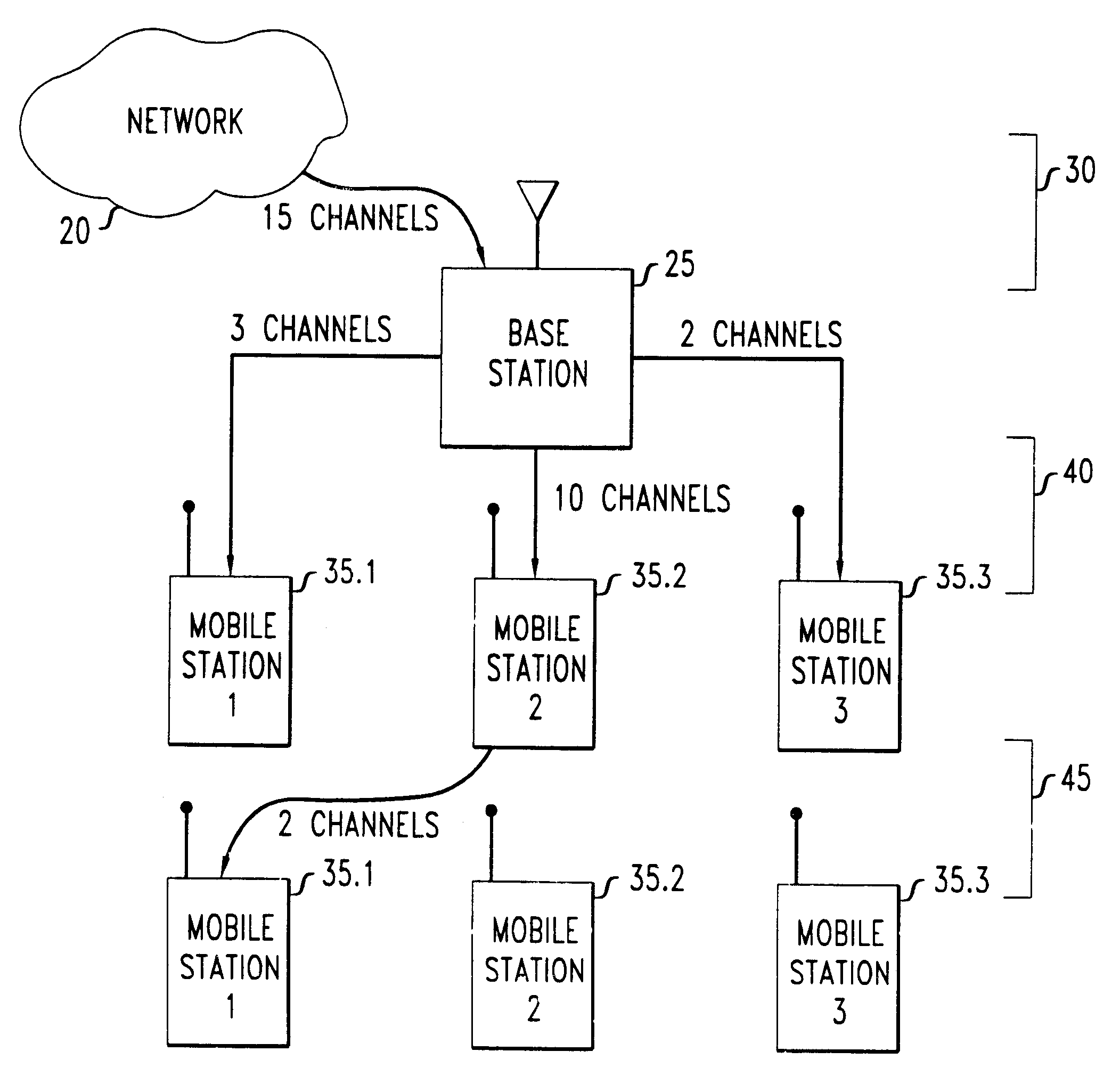
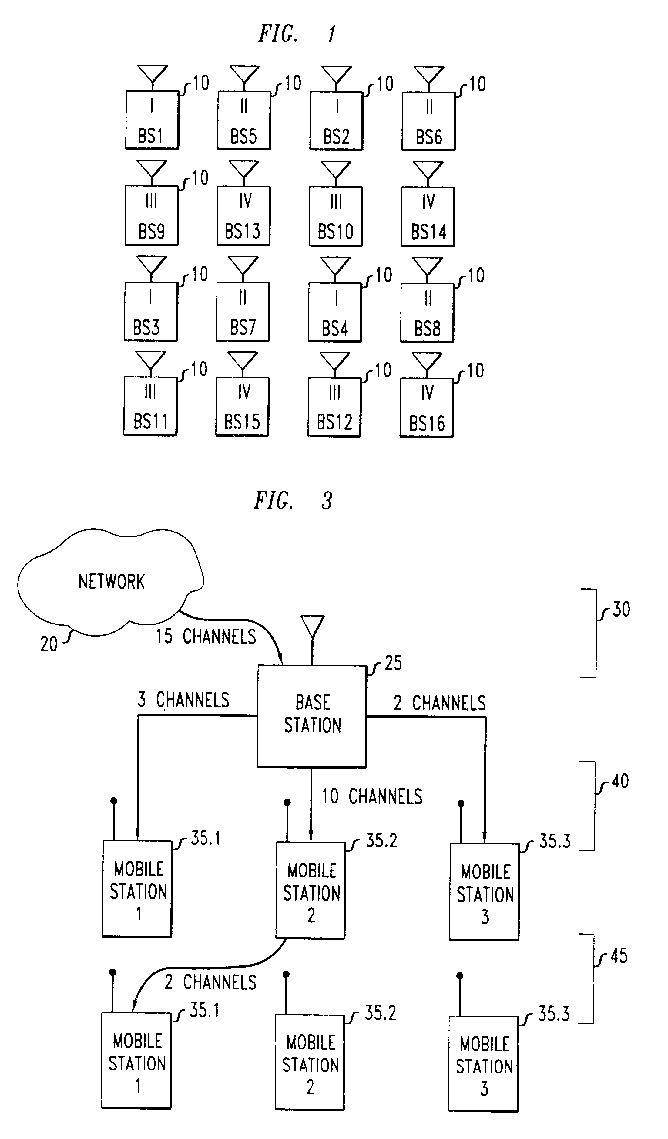
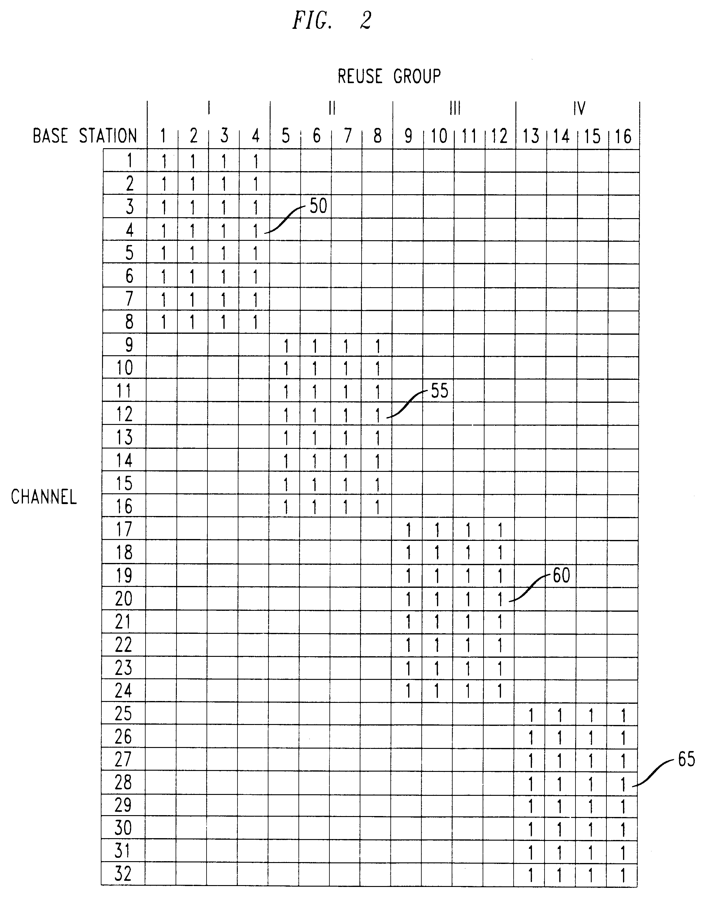
FCA is a planned scheme in which each base station receives a predetermined allocation of channels. These are chosen to keep interference at an acceptable level regardless of which channels are actually being used. Referring to FIG. 1, an illustrative FCA scheme might assign channels 1-8 to base station...


PUM


Abstract

We disclose a method of dynamic channel assignment for wireless transmission systems that employ time or frequency multiplexing, or both time and frequency multiplexing. The invention is specifically addressed to the problem of avoiding interference in the channels of such systems. In a broad aspect, the invention involves partitioning base stations of a network into non-interfering sets. Channels are allocated to the non-interfering sets according to need. Stages of channel reallocation take place periodically. The reallocation takes place through coordinated activity by the base stations. That is, the channel reallocation is carried out in response to information that is exchanged between base stations, or it is centrally directed by the network in response to information passed to the network by the base stations.

Description

This invention relates to methods for operating a packetized wireless communication network in which multiple radio-frequency channels are available for transmitting signals between user terminals such as mobile stations and the base stations that serve them. More specifically, the invention relates to methods for allocating the available channels among a group of base stations according to time-varying and spatially inhomogeneous demands for transmission capacity.ART BACKGROUNDPacketized wireless communication networks, such as cellular telephone networks, are already in wide use for carrying voice traffic. The use of portable personal computers is also widespread. There is now a growing demand for wireless networks to carry high-speed data traffic in addition to voice traffic, so that data can be exchanged, without wired connections, among portable or mobile computers.However, computer-data traffic differs significantly from voice traffic in several respects. Because of these diff...

Claims


Application Information

Patent Timeline
IPC IPC(8): H04L12/56H04Q7/36H04J3/16H04B7/26H04W16/10H04W28/14H04W72/06H04W88/08
CPCH04W16/10H04W28/14H04W28/16H04W72/00H04W88/08
Inventor ANDREWS, DANIEL MATTHEWBORST, SIMON C.DOMINIQUE, FRANCISJELENKOVIC, PREDRAGKUMARAN, KRISHNANWHITING, PHILIP ALFRED
Owner LUCENT TECH INC
Learn More