
Films with improved blocking resistance and surface properties

Inactive Publication Date: 2002-12-17
JINDAL FILMS AMERICAS LLC
View PDF21 Cites 68 Cited by
  • Summary
  • Abstract
  • Description
  • Claims
  • Application Information

AI Technical Summary

Problems solved by technology

Films which are treated on both sides, either with corona or flame treatment, have been used in the past; however, such films have the tendency to become blocked.
This is especially a problem for cavitated films or when one of the surfaces is subsequently metallized since blocking leads to metal pick off and loss of functionality.
Blocking manifests itself as, among other things, undesirable adhesion between layers of polymer films.
In the absence of the slip agent, the layer-to-layer COF is so great that smooth unwinding of the film is virtually impossible.
However, there are many disadvantages with using antiblocking and slip agents in films.
Plate-out, for example, is an objectionable coating of these agents which forms on converting or end-use equipment.
Additionally, these agents may scratch the opposite metal layer in a metallized film which could damage the barrier properties of the film.
Moreover, these agents may interfere or destroy the adhesion of metal coatings to films.

Method used


Image

  • Films with improved blocking resistance and surface properties
  • Films with improved blocking resistance and surface properties
  • Films with improved blocking resistance and surface properties

Examples


example 2

ii. Cavitated Structures

The structure of the film used in the example from which the data is generated is shown below. The thickness of the layer is expressed in gauge (ga) which is 0.00001 inch.

As shown in Table III, different resin types and different additive packages were used to vary the non-print surface. The structure with the impact copolymer skin consistently had the lowest blocking force.

The basic film structure from which the data of Table IV is generated is shown below:

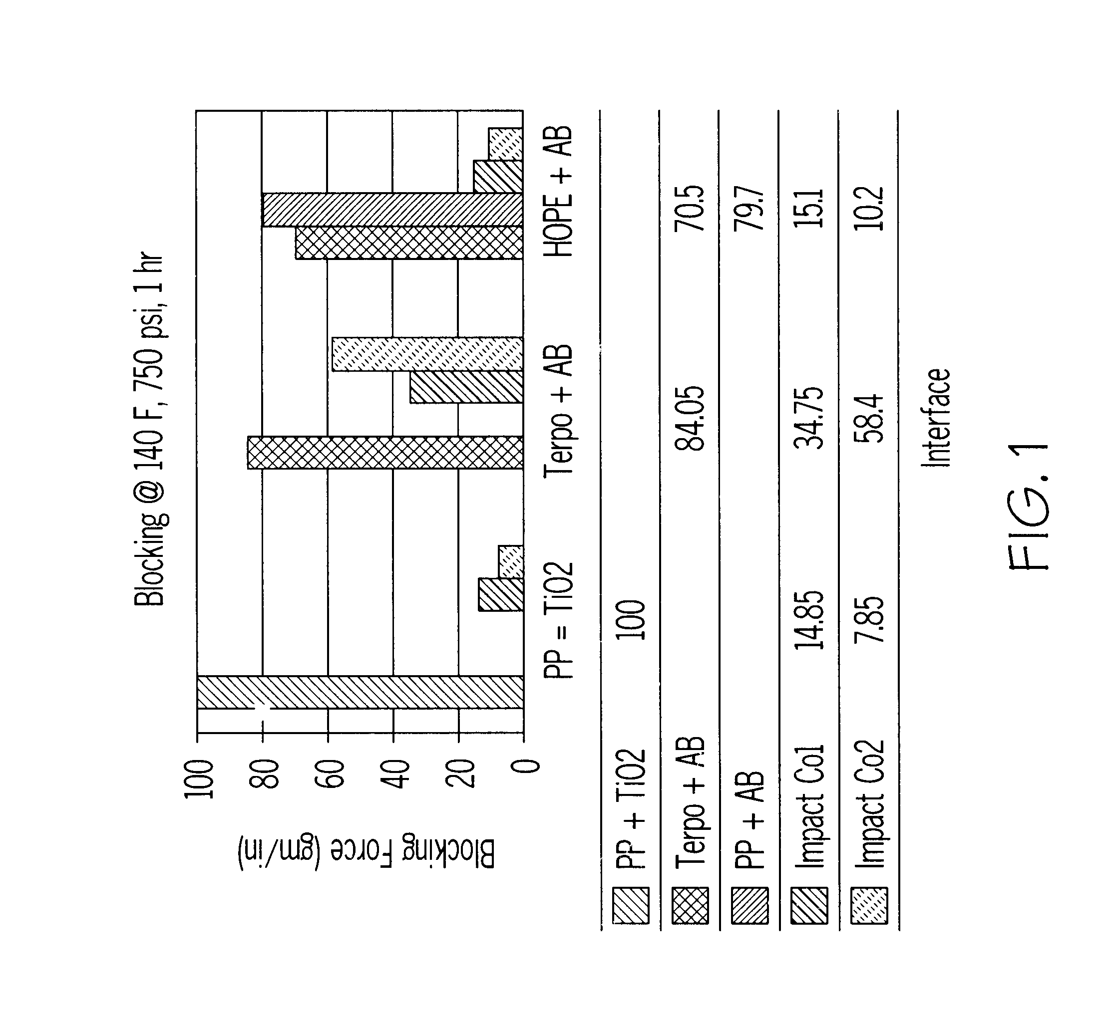
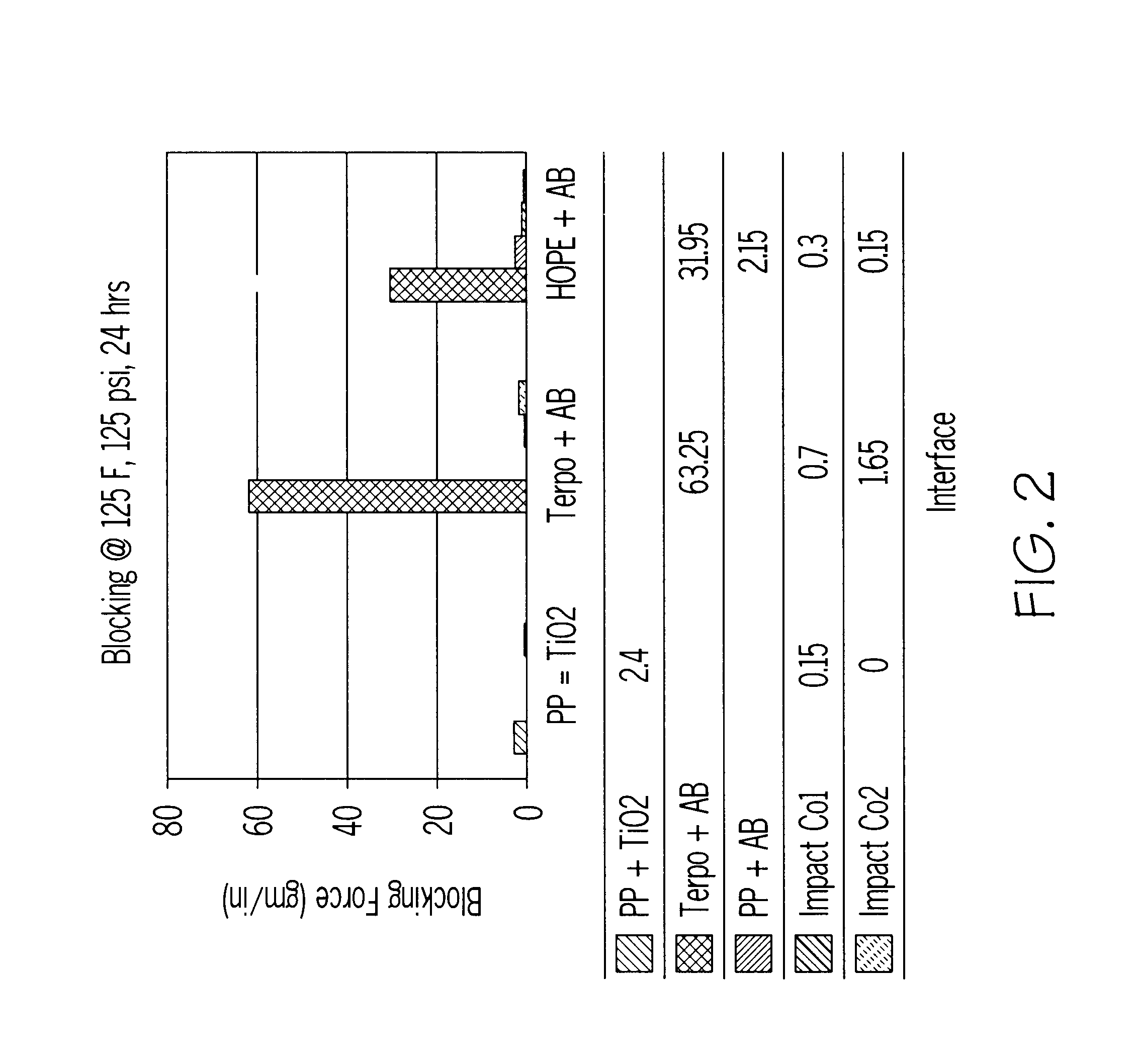
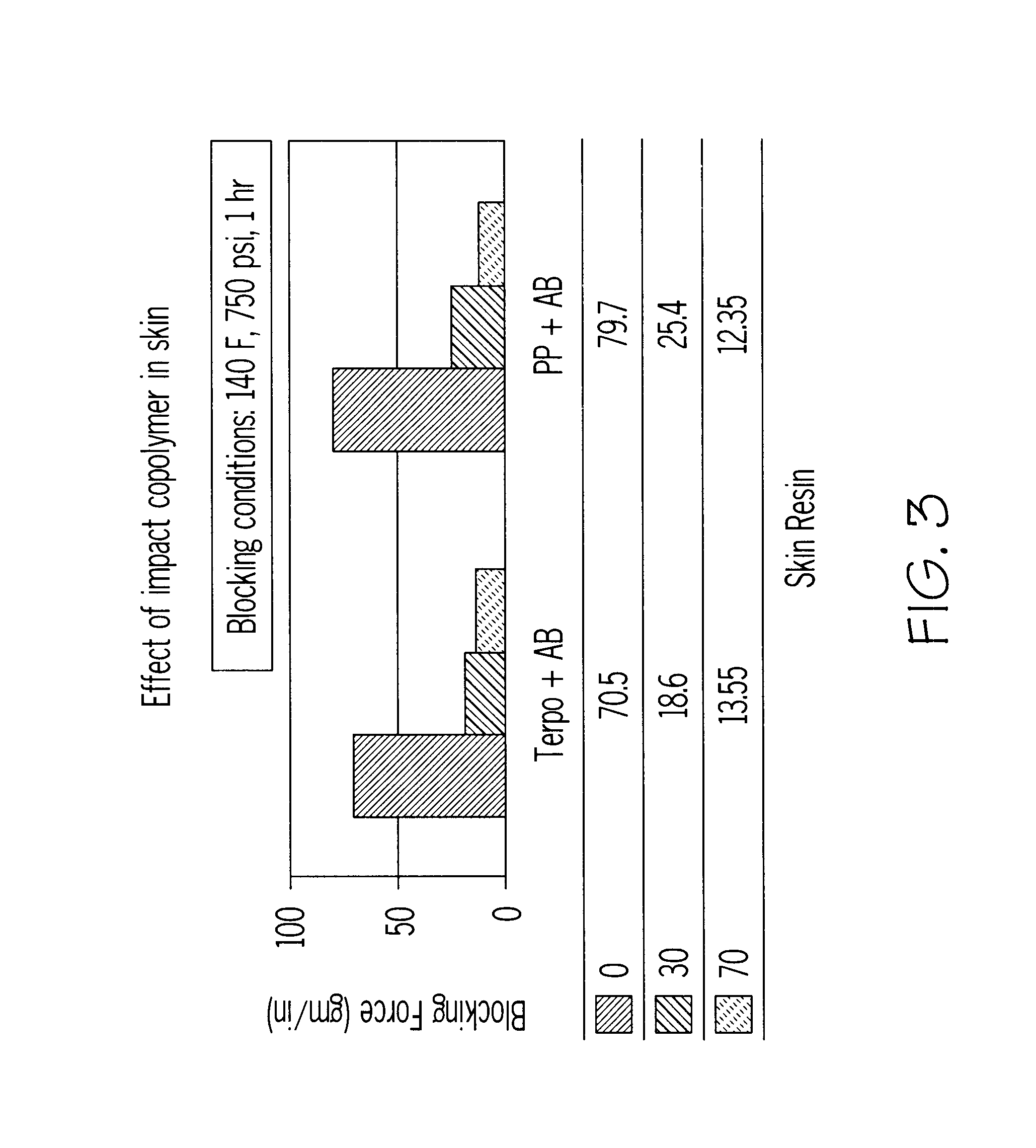
Table IV shows the effect the use of impact copolymer as a skin layer has on blocking forces and COF in multilayer films. In each instance, substituting an impact copolymer skin layer for a homopolymer PP or a EPB terpolymer or a HDPE skin layer lowered the blocking force. The effect was greater at the lower pressure.

FIGS. 1 and 2 show the effect that the using impact copolymer as a skin layer in contrast with using homopolymer polypropylene or terpolymer as a skin layer. The blocking conditions are set at...

example 3

The structure of the film from which the data in FIG. 5 was generated is shown below:

In this example, the impact copolymer is blended into the treated skin resin. The treated surface was tested against itself. The COF of the samples with impact copolymer layers was lowered without the use of antiblock. The COF at a 50% loading was not always better than the 20% loading, so there may be a point at which the effectiveness diminishes or reverses. FIG. 5 is a graph showing this effect.

example 4

Impact Copolymer Used as a Tie Layer

The structure of the film used to generate the data in Table V is shown below:

In these samples, the impact copolymer was used as tie layers. Because the samples were made one side treated only, the treated surface was tested against itself. Both blocking conditions showed reduced blocking force when the tie layers were impact copolymer. The COF of the samples with impact copolymer layers was significantly reduced without the use of antiblock. This effect was particularly dramatic when the skin layer had no antiblock formulated into it. See Table V.

The data in Table VI is generated using the film structure shown below:

In these samples, the impact copolymer is used as the tie layer. One tie layer includes titanium dioxide. Because the sample was made with only one side treated, the treated surface was tested against itself. When the tie layer was impact copolymer, reduced blocking forces were seen under conditions of 125.degree. F. / 125 psi. The COF ...


PUM

PropertyMeasurementUnit
Fractionaaaaaaaaaa
Fractionaaaaaaaaaa
Fractionaaaaaaaaaa

Abstract

The invention discloses methods of improving blocking resistant properties and reducing the coefficient of friction of a multilayer film comprising providing at least one layer of an ethylene-propylene impact copolymer having from about 3% to about 30% by weight ethylene, wherein said copolymer has no more than two peaks in the melting curve within the range from about 110° C. to about 165° C., and wherein said layer is non-heat sealable, to a multilayer film having a core layer comprising polypropylene, high density polyethylene (HDPE) or linear low density polyethylene (LLDPE), whereby anti-blocking and coefficient of friction characteristics of said film is improved without necessity of adding an antiblock or slip agent.

Description

BACKGROUND OF INVENTIONThe invention relates to methods for preparing polymer films. In particular, the invention relates to methods of preparing polymer films with improved blocking resistance and reduced coefficient of friction (COF) without the necessity of adding an antiblock or slip agent.Two side processable films (i.e. two side treated) allow for diverse functionality. For example, the outside of the film may be metallized, printed or laminated and the inside of the film may have cold seal coating and promotional print. Films which are treated on both sides, either with corona or flame treatment, have been used in the past; however, such films have the tendency to become blocked. This is especially a problem for cavitated films or when one of the surfaces is subsequently metallized since blocking leads to metal pick off and loss of functionality. Blocking manifests itself as, among other things, undesirable adhesion between layers of polymer films. Therefore, such films need ...

Claims


Application Information

Patent Timeline
IPC IPC(8): B32B27/32C08J7/00
CPCB32B27/32Y10T428/31Y10S428/91Y10T428/31928Y10T428/31913Y10T428/31909Y10T428/31692B32B2255/205B32B2255/26B32B2255/10B32B27/08B32B2307/746
Inventor MIGLIORINI, ROBERT A.
Owner JINDAL FILMS AMERICAS LLC
Learn More