
Vehicle air conditioner with heating capacity control of cooling water circuit

a technology of cooling water circuit and heating capacity control, which is applied in vehicle heating/cooling devices, transportation and packaging, and electrical generators. it can solve the problems of insufficient heating effect, insufficient heat quantity, and ineffective use of unnecessary heat discharged from the engin

Inactive Publication Date: 2002-09-24
DENSO CORP
View PDF11 Cites 70 Cited by
  • Summary
  • Abstract
  • Description
  • Claims
  • Application Information

AI Technical Summary

Benefits of technology

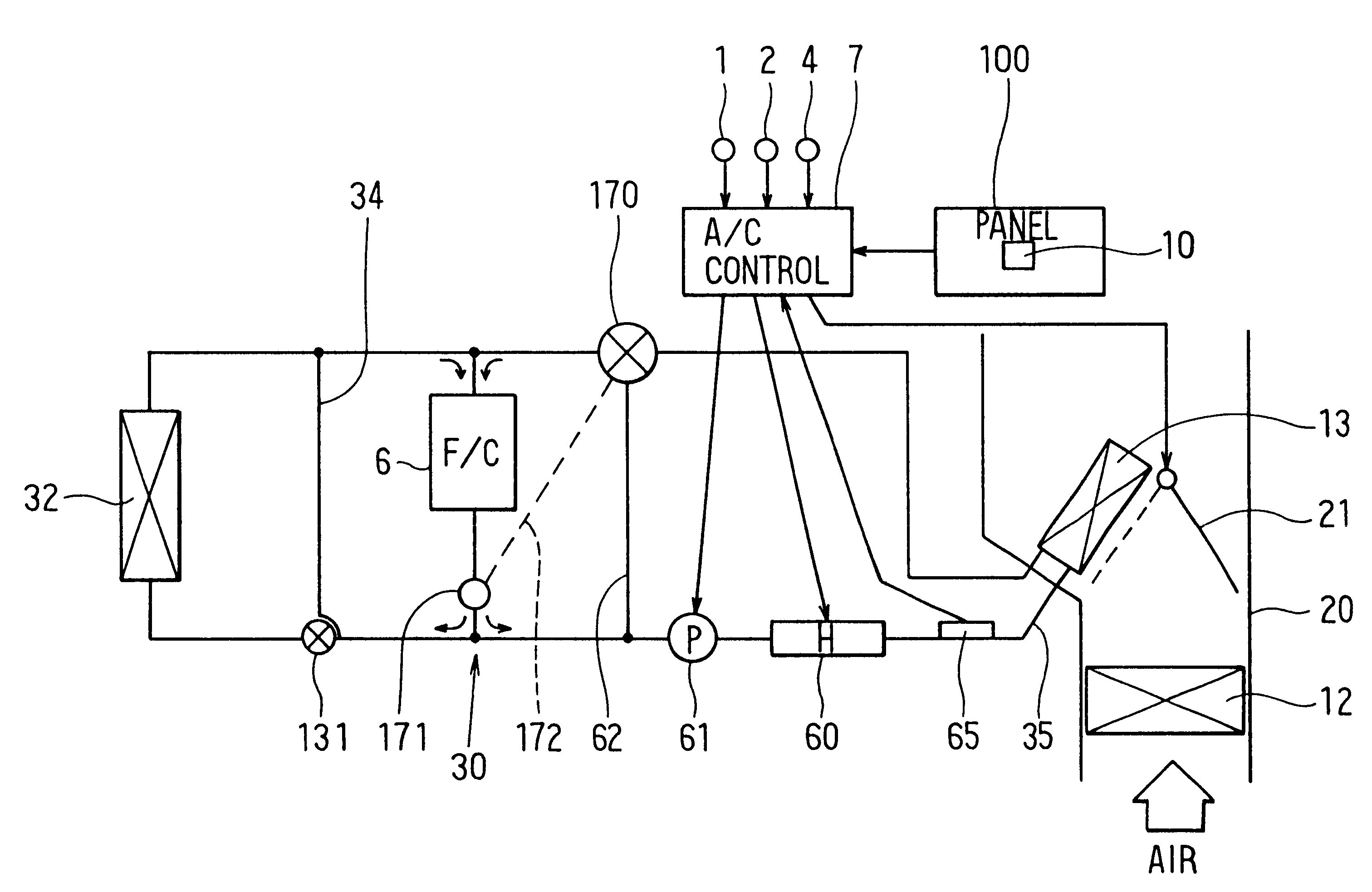
According to the present invention, in an air conditioner for a vehicle having an equipment that needs a temperature control, a heating heat exchanger for heating air to be blown into a passenger compartment using cooling water as a heating source is disposed in a cooling water circuit, a supplementary heater for heating air is used for supplementing a heat quantity relative to the heating heat exchanger, a necessary heat quantity necessary for a heating of air blown into the passenger compartment is calculated based on a target air temperature, and a flow control unit controls a flow of cooling water in the cooling water circuit in such a manner that: cooling water from the equipment flows into the heating heat exchanger after temperature of the equipment increases to a predetermined temperature, and the flow of cooling water from the equipment to the heating heat exchanger is interrupted until the temperature of the equipment increases to the predetermined temperature. In the vehicle air conditioner, a heat quantity generated by the supplementary heater is used for supplementing an insufficient heat quantity when the heat quantity for heating air in the heating heat exchanger is smaller than the necessary heat quantity, after the temperature of the equipment increases to the predetermined temperature. Accordingly, when the temperature of the equipment increases the predetermined temperature, a surplus heat quantity unnecessary for the temperature control of the equipment is supplied to the heating heat exchanger. Therefore, even when the surplus heat quantity is a little, it can be effectively used for heating air. Further, when the surplus heat is insufficient for obtaining the necessary heat quantity in the heating heat exchanger, the insufficient heat quantity is supplemented by the supplementary heater. As a result, a predetermined heating capacity can be obtained.
On the other hand, until the temperature of the equipment increases to the predetermined temperature for a normal operation of the equipment, that is, when there is not the surplus heat discharged from the equipment, the flow of cooling water flowing into the heating heat exchanger is interrupted. Therefore, in this case, the temperature of the equipment can be rapidly increased, and it can prevent the temperature of the equipment from being lowered due to heat radiation from the heating heat exchanger. Even in this case, a heat-generating amount of the supplementary heater is controlled, so that the predetermined heating capacity can be obtained.

Problems solved by technology

When the heating of the passenger compartment is performed using cooling water of the water-cooled engine, a sufficient heating effect cannot be obtained when temperature of cooling water is low.
However, in this vehicle air conditioner, even when the temperature of cooling water in the engine increases and surplus heat is generated from the engine, when the temperature of cooling water in the engine is not increased to a temperature for obtaining the sufficient heating effect in the heater core, the heating of the passenger compartment is performed using the heat from the electrical heater in the closed water circuit.
Accordingly, in this case, unnecessary heat discharged from the engine is not effectively used.
Further, when the surplus heat is insufficient for obtaining the necessary heat quantity in the heating heat exchanger, the insufficient heat quantity is supplemented by the supplementary heater.

Method used


Image

  • Vehicle air conditioner with heating capacity control of cooling water circuit
  • Vehicle air conditioner with heating capacity control of cooling water circuit
  • Vehicle air conditioner with heating capacity control of cooling water circuit

Examples


first embodiment

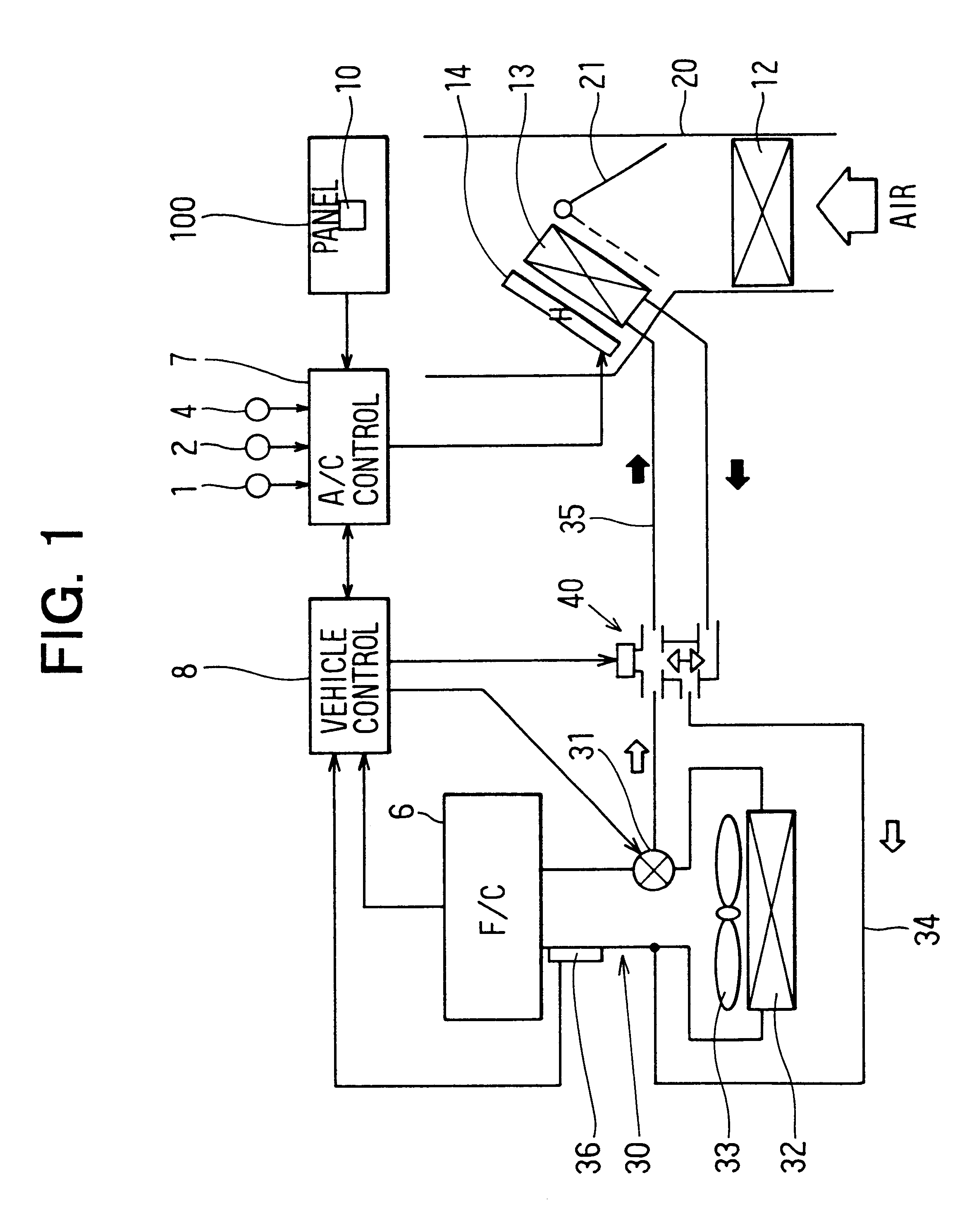
A first preferred embodiment of the present invention will be now described with reference to FIGS. 1-4. In the first embodiment, the present invention is typically applied to an air conditioner for a fuel-cell powered vehicle. As shown in FIG. 1, a fuel cell system (F / C) 6 that is an equipment needed to perform a temperature control is connected to a cooling water circuit 30. The fuel cell system 6 has therein a water pump (not shown) so that cooling water for cooling the fuel cell system 6 is circulated in the cooling water circuit 30.

A radiator 32, for radiating a surplus heat of cooling water to an outside of a passenger compartment, is disposed in the cooling water circuit 30. The cooling water circuit 30 has a first cooling water passage 34 through which cooling water bypasses the radiator 32 when it is unnecessary to radiate heat of cooling water to the outside of the passenger compartment. A three-way valve 31 for distributing cooling water from the fuel cell system 6 is dis...

third embodiment

In the third embodiment, as shown in FIG. 6, a control valve 80 is used instead of the above-described control valve 40. The control valve 80 has therein a first inlet 81 from which cooling water from the fuel cell system 6 flows into the control valve 80, a second inlet 83 from which cooling water from the heater core 13 flows into the control valve 80, and an outlet 84 from which cooling water in the control valve 80 flows toward the fuel cell system 6. A valve body 85 is rotatably disposed in the control valve 80, so that a first passage 90 from the first inlet 81 to the outlet 84, and a second passage 91 from the second inlet 83 to the outlet 84 are defined in the control valve 80.

The control valve 80 has a controller 88 made of a servomotor. The valve body 85 is controlled by the controller 88 to be rotated by a predetermined rotation angle. By adjusting a rotation angle of the valve body 85, an opening area ratio between the first passage 90 and the second passage 91 can be ad...

fourth embodiment

In the fourth embodiment, the fuel cell system 6 is connected to the cooling water circuit 30 as shown in FIG. 7. The cooling water circuit 30 has a first cooling water passage 34 through which cooling water circulates at a left side circuit of the fuel cell system 6 in FIG. 7, and a second cooling water passage 35 through which cooling water circulates at a right side circuit of the fuel cell system 6 in FIG. 7, including the heater core 13. A water pump (not shown) is provided within the fuel cell system 6 so that cooling water circulates in the cooling water circuit 30. By cooling water circulating in the cooling water circuit 30, temperature of the fuel cell system 6 is controlled (cooled) in a suitable temperature range (e.g., 72-80.degree. C.) where the electrical-power generating effect of the fuel cell system 6 can be made suitable. Generally, the fuel cell system 6 operates normally in the suitable temperature range (e.g., 72-80.degree. C.).

The radiator 32 is disposed so th...


PUM

PropertyMeasurementUnit
temperatureaaaaaaaaaa

Abstract

In a vehicle air conditioner where air blown into a passenger compartment is heated in a heater core using cooling water for cooling a fuel cell system as a heating source, a flow amount of cooling water flowing into the heat core is controlled by a control valve based on a surplus heat quantity of the fuel cell system and a necessary heat quantity of the passenger compartment. Further, when the surplus heat quantity of the fuel cell system is smaller than the necessary heat quantity, an insufficient heat quantity is supplemented by a supplementary heater.

Description

This application is related to Japanese Patent Applications No. 2000-56974 filed on Mar. 2, 2000, and No. 2000-319313 filed on Oct. 19, 2000, the contents of which are hereby incorporated by reference.1. Field of the InventionThe present invention relates to a vehicle air conditioner with a heating capacity control in a cooling water circuit having a heating heat exchanger for heating air. In the cooling water circuit, cooling water heated by an equipment that needs a temperature control circulates in the heating heat exchanger.2. Description of Related ArtIn a vehicle air conditioner, heating of a passenger compartment is performed using cooling water from an equipment that needs a temperature control, such as a water-cooled engine, as a heating source. When the heating of the passenger compartment is performed using cooling water of the water-cooled engine, a sufficient heating effect cannot be obtained when temperature of cooling water is low.To overcome this problem, in a vehicl...

Claims


Application Information

Patent Timeline
Patent Type & Authority Patents(United States)
IPC IPC(8): B60H1/00B60H1/03B60H1/02B60H1/08B60H1/22B60L1/08B60L11/18H01M8/00
CPCB60H1/00485B60H1/00792B60H1/00885B60H1/034B60H1/2215B60H2001/00128
Inventor MATSUNAGA, KENTANAKA, MASAYAIEDA, HISASHI
Owner DENSO CORP
Learn More