
Multiple-clutch device

a multi-clutch, clutch technology, applied in the direction of clutches, non-mechanical actuated clutches, climate sustainability, etc., can solve the problems of high slippage, correspondingly extensive heat generation, and loss of operation, and achieve the effect of enhancing operating performan

Inactive Publication Date: 2002-09-24
VOLKSWAGEN AG +1
View PDF13 Cites 67 Cited by
  • Summary
  • Abstract
  • Description
  • Claims
  • Application Information

AI Technical Summary

Benefits of technology

is generally to achieve improvements with respect to at least one of the problems and / or other problems mentioned above. In particular, an objective of the invention is to provide a multiple-clutch device with advantageous operating performance, for example, with respect to operating reliability, and / or a multiple-clutch device which can be constructed in a compact manner.
The sealing arrangement can have a sealing element which is arranged at a wall portion defining the pressure compensation chamber and can engage tightly with the latter and with the actuating piston. The sealing element can project from the wall portion in the direction of the stop face of the actuating piston and, at least in the engaged state of the clutch arrangement, can transmit elastic restoring forces to the actuating piston in the direction of a stroke position corresponding to a released state of the clutch arrangement. The sealing element can be injection-molded at an edge area of the wall portion or can be fitted over the edge area. This is particularly simple in terms of assembly and, moreover, provides for a secure positioning of the sealing element at the wall portion.
As a result of the above-mentioned guiding of the actuating piston at the plate carriers, the actuating piston is axially guided in a secure manner so that high operating reliability is achieved and, on the other hand, an especially compact construction of the clutch device is made possible, since no separate guide elements are required for guiding the piston and installation space can accordingly be economized on. When a centrifugal force pressure compensation chamber is provided, which receives the pressure compensation medium and is defined or limited by the actuating piston, the actuating piston can also guide the centrifugal force pressure compensation chamber at the plate carrier in a sealing manner.
When a labyrinth seal of the type mentioned above is provided, separate sealing elements made of rubber, plastic or elastomer material, for example, can be dispensed with and the seal and associated counter-element can be made of the same material with, consequently, the same thermal coefficient of expansion. It is extremely advantageous for both sealing members of the labyrinth seal to have the same thermal coefficient of expansion insofar as temperature changes or temperature fluctuations cause no changes, or no substantial changes, in the engagement or frictional engagement, as the case may be, between the sealing members which would lead to corresponding fluctuations in inertial forces to be overcome during the engaging and disengaging movement of the piston. Further, there are no substantial fluctuations in the sealing action, especially no loss of tightness.
The other constructional variant according to the invention with the sealing ring which is fixed on one side and engages with axial play on the other side is advantageous insofar as particularly good sealing can be achieved, for example, when the sealing ring is additionally acted upon by the pressure in the pressure chamber or pressure compensation chamber to strengthen the sealing engagement in such a way that the sealing ring is pressed more firmly into a shaped portion receiving the sealing ring. This takes place to a marked degree in the case of the pressure chamber when the clutch is engaged with the stationary piston in its moved out or disengaged position, i.e., when the plate stack is tensioned to a maximum degree and as little leakage as possible should occur.
When the sealing ring is inserted into a shaped portion or cutout of the actuating piston on one side and acts at the plane surface portion on the other side, axial installation space can be economized on in that the shaped portion is provided in the edge area of a radially extending piston portion. Thin wall thicknesses are made possible in this way. The shaped portion, possibly, a groove, can then be rolled in if desired. In order to economize on axial installation space, it is also helpful that the sealing ring can be elongated in cross section in radial direction as suggested according to the invention without the risk of impairing the sealing action.

Problems solved by technology

Obviously, starting processes of the type described above lead to high slippage with a correspondingly extensive development of heat.
This presents the problem of carrying away this heat from the area of the friction clutch serving as starting clutch.
Further, a correspondingly high wear of the friction clutch must be taken into account.
Moreover, heating of the friction clutches is accompanied by changes in the coefficient of friction of the friction clutches, so that control of the release mechanisms of the two friction clutches, and therefore control of the two friction clutches relative to one another, can be appreciably impaired.
Since inaccuracies or changes in the functional matching of the two friction clutches relative to one another caused by heat can have the result that a torque ratio not intended in the shifting process is applied to the transmission input shafts, shifting processes in the shift transmission can be subjected to load.
The synchronization in the shift transmission can be overtaxed in this way, so that, in the worst case, the shift transmission can be damaged to the point of complete failure, apart from disadvantages with respect to efficiency which occur in any case.
On the whole, mismatching between the two friction clutches caused by heat is incompatible with a problem-free torque transmission in shifting processes in the shift transmission without interruption of tractive force and without jerking during shifting.
Another problem area in a double-clutch device relates to starting processes carried out in opposition to an inclination, wherein the motor vehicle must be prevented from rolling backward, or those which are used when parking at the lowest possible speed, for example, for precise positioning of a motor vehicle in a parking space.
Although the torques to be transmitted in such starting processes lie well below those occurring under the operating conditions described above, especially in car racing, an intensive heating of the respective friction clutch or even both friction clutches can occur, resulting in the problems detailed above.
The risk of intensive overheating exists not only in a dry friction clutch, but can also occur in so-called "wet" friction clutches, in the form of a disk or plate clutch, which are operated by the action of a viscous operating medium such as hydraulic fluid.
In spite of the liquid cooling, heating of the friction clutches is also a considerable problem in plate clutches because the operating medium, which usually flows through friction facing grooves or the like to carry off the heat, cannot be guided between the plates in optional quantity.
The reason for this is that, on one hand, excessive flow through the friction facing grooves or the like would build up a counterpressure between the friction surfaces of two adjacent plates and would therefore reduce the capacity of the friction clutches to transmit torque (with a corresponding increase in slip and therefore additional generation of friction heat, so that the problem of overheating is exacerbated) and, on the other hand, the operating medium could be overheated and destroyed when flowing through between the plates.
Overheating in plate clutches can result in that the friction surfaces can no longer separate from one another completely during a disengaging process and, consequently, torques can still be transmitted via the clutch which should be disengaged, so that considerable drag torques can reach the associated shift transmission.
Within the framework of investigations undertaken by the present Applicants in connection with double-clutch devices, it was shown in general that wet-type clutches exhibit sealing problems and problems relating to output losses.
Further, it was shown that boundary conditions relating to the available axial and radial installation space could be adhered to only with difficulty, if at all, based on the previously known concepts.
With regard to clutches, possibly, diaphragm clutches, which are actuated by pistons integrated in the clutch device, the arrangement of the piston chambers associated with the pistons proved especially problematic.

Method used


Image

  • Multiple-clutch device
  • Multiple-clutch device
  • Multiple-clutch device

Examples


Embodiment Construction

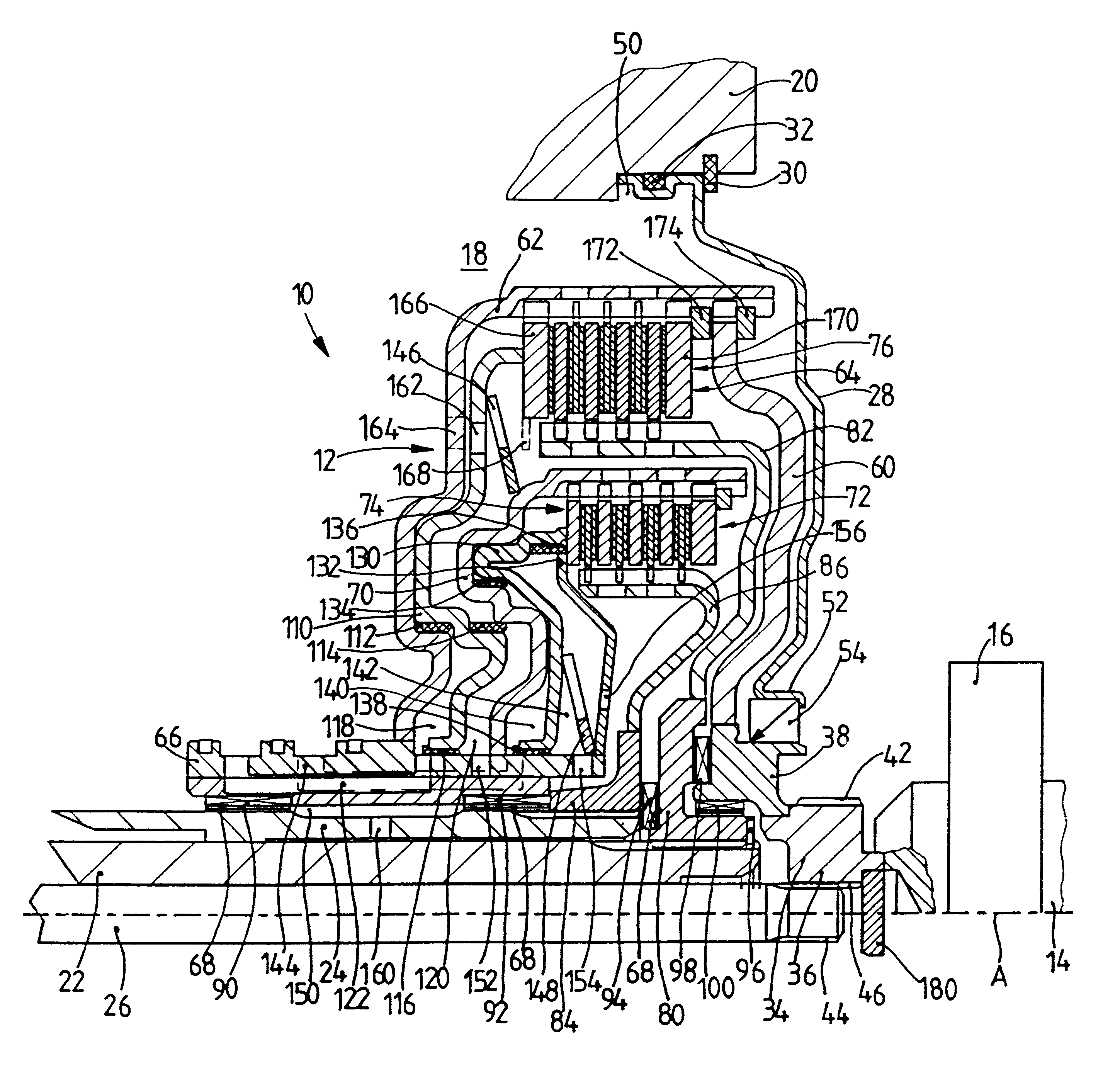
FIG. 1 shows a double-clutch 12 arranged in a drivetrain 10 between a drive unit and a transmission. The drive unit, for example, an internal combustion engine, is represented in FIG. 1 only by a driven shaft 14, such as a crankshaft 14, with a coupling end 16 serving to connect a torsional vibration damper, not shown. In FIG. 1, the transmission is represented by a transmission housing portion 20 defining a transmission housing cover 18 and by two transmission input shafts 22 and 24, both of which are constructed as hollow shafts, wherein transmission input shaft 22 extends through transmission input shaft 24 substantially coaxial thereto. A pump drive shaft which serves to drive a transmission-side oil pump, not shown in FIG. 1, as will be described more fully in the following, is arranged in the interior of the transmission input shaft 22.

The double-clutch 12 is received in the transmission housing cover 18, wherein the interior of the cover is closed in the direction of the driv...


PUM


Abstract

The invention is directed to a multiple-clutch device, such as a double-clutch device, for arranging in a drivetrain of a motor vehicle between a drive unit and a transmission, wherein the clutch device has a first clutch arrangement associated with a first transmission input shaft of the transmission and a second clutch arrangement associated with a second transmission input shaft of the transmission for transmitting torque between the drive unit and the transmission. According to one aspect of the invention, it is suggested that at least one of the clutch arrangements has an actuating piston defining a pressure chamber for actuation, preferably for engagement of the clutch arrangement by means of a pressure medium, preferably a hydraulic medium, wherein the actuating piston divides the pressure chamber from an associated centrifugal force pressure compensation chamber which receives a pressure compensation medium.

Description

1. Field of the InventionThe invention is directed to double-clutch device, for arranging in a drivetrain of a motor vehicle between a drive unit and a transmission, wherein the clutch device has a first clutch arrangement associated with a first transmission input shaft of the transmission and a second clutch arrangement associated with a second transmission input shaft of the transmission for transmitting torque between the drive unit and the transmission.2. Description of the Related ArtA clutch device of this type is known, for example, from EP 0 931 951 A1. The clutch device serves to connect the drive of a motor vehicle with a multiple-speed shift transmission via two friction clutches which are preferably automatically actuated, wherein a disengagement or release system is allocated to each of these two friction clutches, so that the two friction clutches can be engaged or released independently from one another. A clutch disk of one of the two friction clutches is arranged o...

Claims


Application Information

Patent Timeline
IPC IPC(8): F16D25/0638F16D25/06F16D25/10F16D21/00F16D21/06F16D25/00F16D48/00F16D25/12F16D48/02
CPCF16D21/06F16D25/0638F16D25/10F16D25/12F16D25/14F16D48/02F16D2021/0661Y02T10/76F16D2048/0263F16D48/0206F16D2048/029F16D2500/1026F16D2500/10412F16D2500/5106F16D25/123F16D47/06F16D2048/0224F16D2048/0233F16D2500/1082
Inventor KUNDERMANN, WOLFGANGSUDAU, JORG
Owner VOLKSWAGEN AG
Learn More