
Piezoelectric actuator

Inactive Publication Date: 2002-09-17
ROBERT BOSCH GMBH
View PDF3 Cites 22 Cited by
  • Summary
  • Abstract
  • Description
  • Claims
  • Application Information

AI Technical Summary

Benefits of technology

It is therefore the principal object of the invention to make a piezoelectric actuator in such a way that reliable cooling of the actuator body that heats up during operation is possible without using liquid coolant. Another object of the invention is the piezoelectric actuator can be installed in a simple way and does not require any special seals as in the case of cooling with liquid.
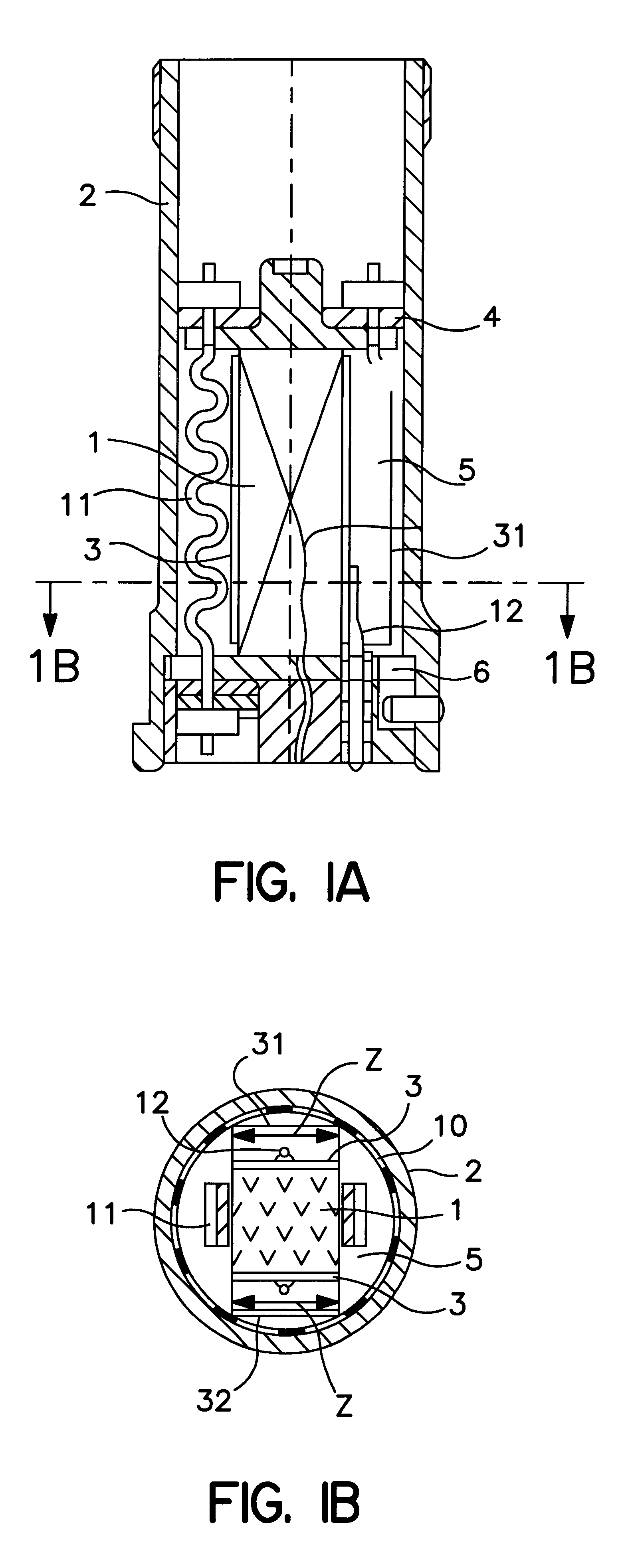
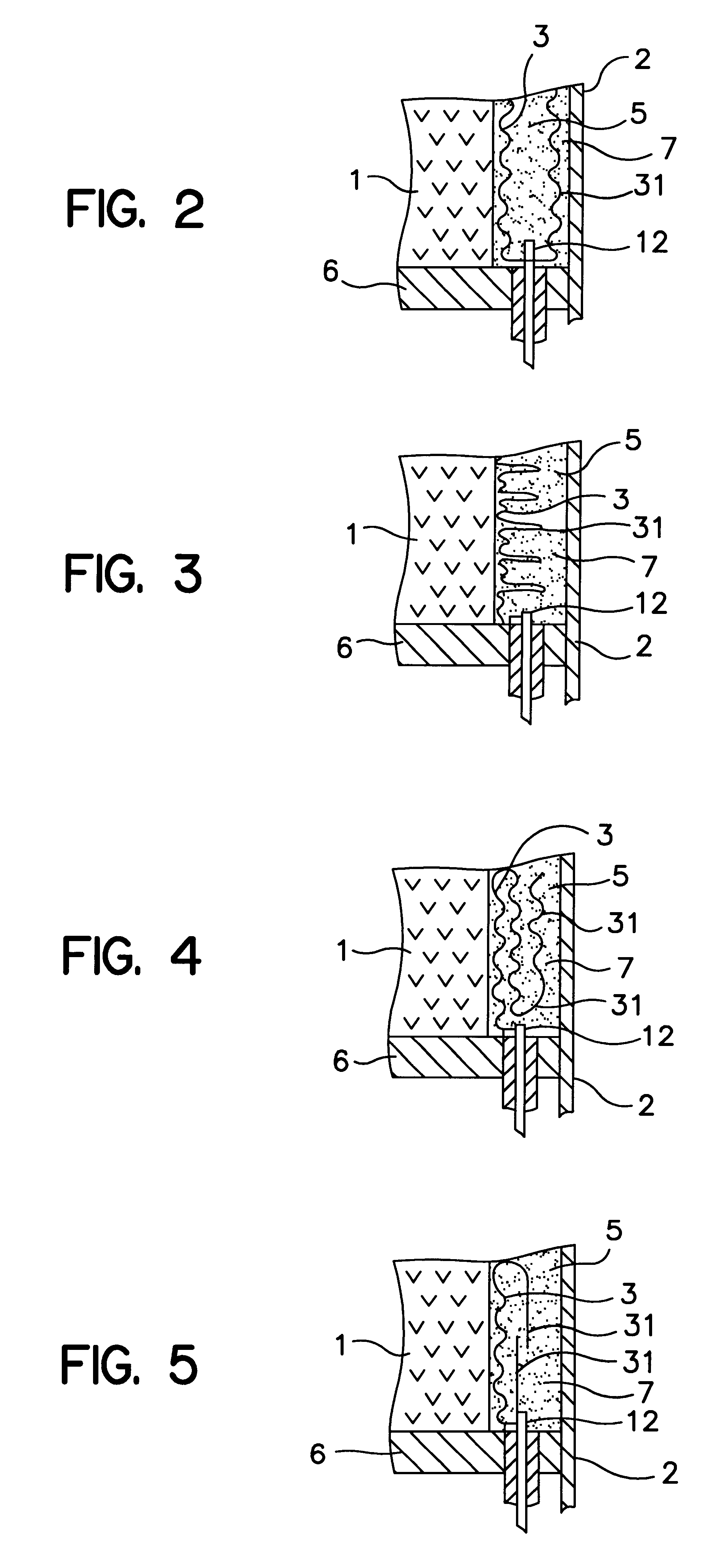
In still another embodiment for enlarging the heat-dissipating surface area of the common electrode leads, a lengthening of the lead wires can also be considered. Once again, the wire length and thus the heat-yielding surface area of the lead wire can be increased by folding it inside the interstice between the actuator body and the module wall.
A piezoelectric actuator designed with the above characteristics utilizes the common electrode leads, located on the outside, which for the sake of good heat dissipation have been lengthened or enlarged, to dissipate the heat from the actuator. Thus solely solid bodies are utilized for heat dissipation, and hence no leakage problems of the kind that sometimes occur if the actuator is liquid-cooled can arise. By sheathing the actuator body with an elastomer or the like, no risk of short-circuiting from splashing water or other dirt occurs.

Problems solved by technology

However, in the design of a piezoelectric actuator, it must be noted that internal losses in the piezoelectric body of the actuator cause lost heat, which has to be dissipated so that the actuator will not overheat.
Since the ceramic materials of the piezoelectric ceramic have poorer heat conductivity, the dissipation inside the actuator body, which substantially comprises ceramic material, is unfavorable, especially in long actuators, whose length is greater than their width.
Cooling the actuator with a liquid coolant, such as fuel, water, motor oil and the like, which is theoretically possible, is unfavorable, first because of the risk of a short circuit from the water component that is contained both in the fuel and in motor oil, and second because the actuator module is more expensive because of complicated seals, which must preclude the coolant used from escaping from the actuator module, especially when the actuator becomes heated.

Method used


Image

  • Piezoelectric actuator
  • Piezoelectric actuator
  • Piezoelectric actuator

Examples


Embodiment Construction

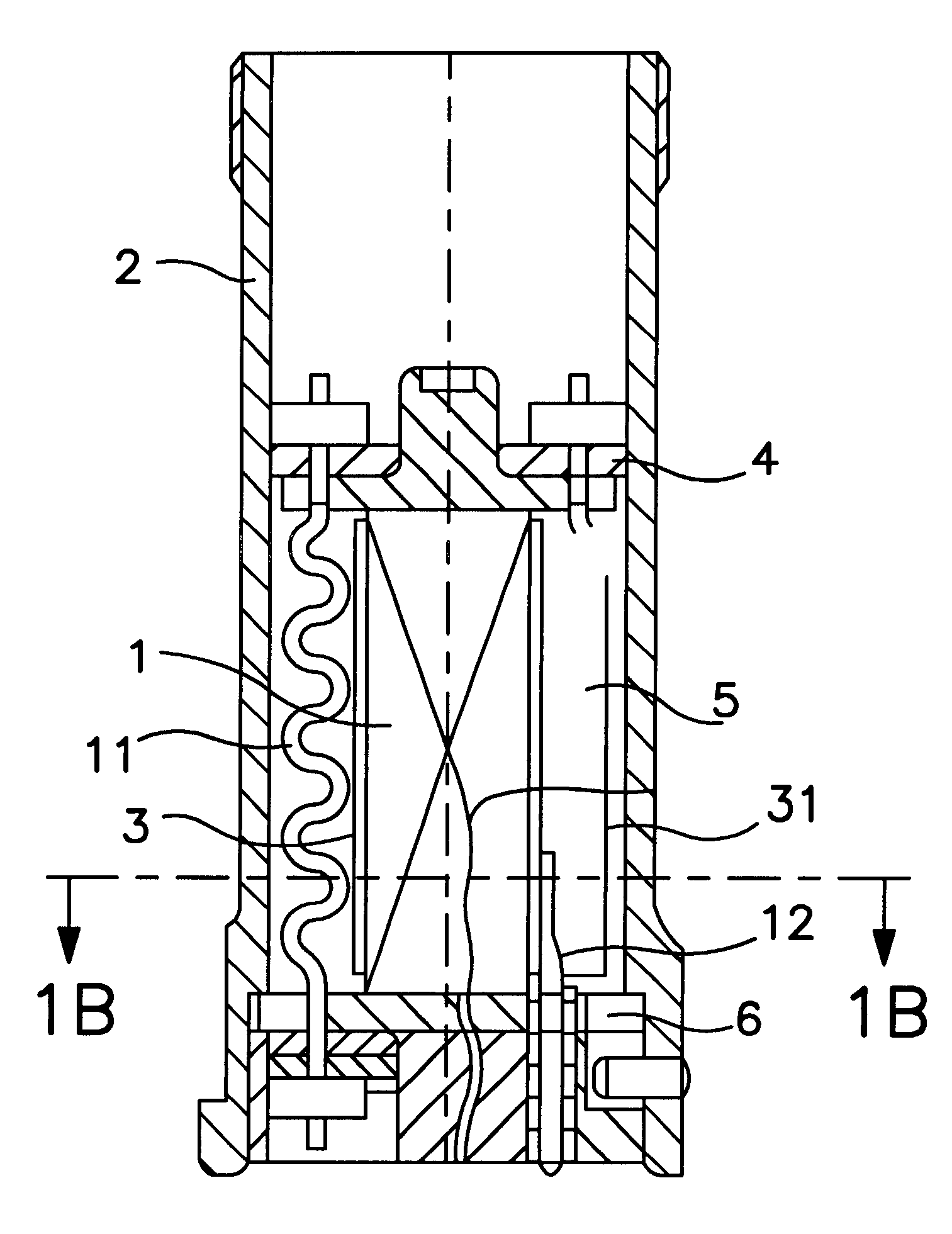
In the first exemplary embodiment, shown in fragmentary longitudinal section in FIG. 1A, of a piezoelectric actuator of the invention, an actuator body 1, which can take the form of a multilayer laminate of stacked layers of piezoelectric material and metal or electrically conductive layers between them and acting as electrodes, is elastically prestressed with its face ends on the left and right by two spring bands (not shown) between a lower metal actuator base 6 and an upper, axially movable plate 4 located on the actuator head and embodied as a partition. The actuator module is enclosed by a metal module wall 2. It should be noted that FIG. 1A shows only the left-hand spring band 11. The spring bands used for the prestressing can also be replaced by a compression spring that presses on the movable plate 4.

Located on both outer long sides of the actuator body 1 in FIG. 1B are common conductive electrode leads 3, which are each contacted with the individual electrode layers extende...


PUM


Abstract

A piezoelectric actuator for actuating control valves or injection valves in internal combustion engines in motor vehicles. The piezoelectric actuator body is in the form of a multilayer laminate of layered plies of piezoelectric material and intervening metal, for instance electrically conductive layers acting as electrodes. The electrode layers are contacted by electrically conductive common electrode leads, and the actuator body is surrounded by a metal module wall which encircles an interstice that contains the common electrode leads. The common electrode leads are designed in the form of a three-dimensionally structured surface or a three-dimensionally structured body, and a portion thereof contacting the actuator body has a lengthened portion or enlargement, that protrudes into the interstice, for dissipating heat from the actuator body, and an elastomer filling with heat-conducting additive particles in the interstice.

Description

The invention is directed to improvements in piezoelectric actuators, in particular for actuating control valves or injection valves in internal combustion engines in motor vehicles, having a piezoelectric actuator body, in particular in the form of a multilayer laminate comprised of layered plies of piezoelectric material and intervening metal or electrically conductive layers acting as electrodes, these electrode layers being contacted by electrically conductive common electrode leads, and the actuator body is surrounded by a metal module wall while maintaining an interstice that contains the common electrode leads.One such piezoelectric actuator is disclosed for instance in German Patent Disclosure DE 196 50 900 A1 of Robert Bosch GmbH.As is well known, piezoelectric actuators can for instance be used for injection valves of a vehicle motor and in brake systems with anti-lock and traction control systems.Such injection valves equipped with piezoelectric actuators have an injectio...

Claims


Application Information

Patent Timeline
IPC IPC(8): F02M59/46F02M59/00F02M51/06F02M47/02H01L41/083H01L41/00H01L41/047H01L41/053F02M63/00F16K31/00F16K31/02H02N2/00H02N2/04
CPCF02M47/027F02M51/0603F02M63/0026H01L41/053H01L41/083H01L41/0472H10N30/872H10N30/883H10N30/886F16K31/00
Inventor HEINZ, RUDOLFSCHMOLL, KLAUS-PETER
Owner ROBERT BOSCH GMBH
Learn More