
Cooling arrangement of a wind turbine

a cooling arrangement and wind turbine technology, applied in the direction of liquid fuel engines, vessel construction, marine propulsion, etc., to achieve the effect of avoiding dangerous situations for helicopters, preventing air congestion, and preventing complex turbulent airflow and ground effects

Active Publication Date: 2012-11-08
SIEMENS GAMESA RENEWABLE ENERGY AS
View PDF15 Cites 15 Cited by
  • Summary
  • Abstract
  • Description
  • Claims
  • Application Information

AI Technical Summary

Benefits of technology

[0006]To ensure a reliable cooling by the surrounding air moving through the radiator, the radiator is mounted in a way that the surrounding air can easily flow through the radiator. The radiator is mounted mainly in the right angel of the direction of the air flow when the turbine is in operation. The radiator is mounted on top of the nacelle to use the maximum of the air flow and to provide a good access for maintenance.

Problems solved by technology

One aim of the installation is to keep salty air out of the nacelle, as salty air will damage the installation in the nacelle.

Method used


Image

  • Cooling arrangement of a wind turbine
  • Cooling arrangement of a wind turbine
  • Cooling arrangement of a wind turbine

Examples


Embodiment Construction

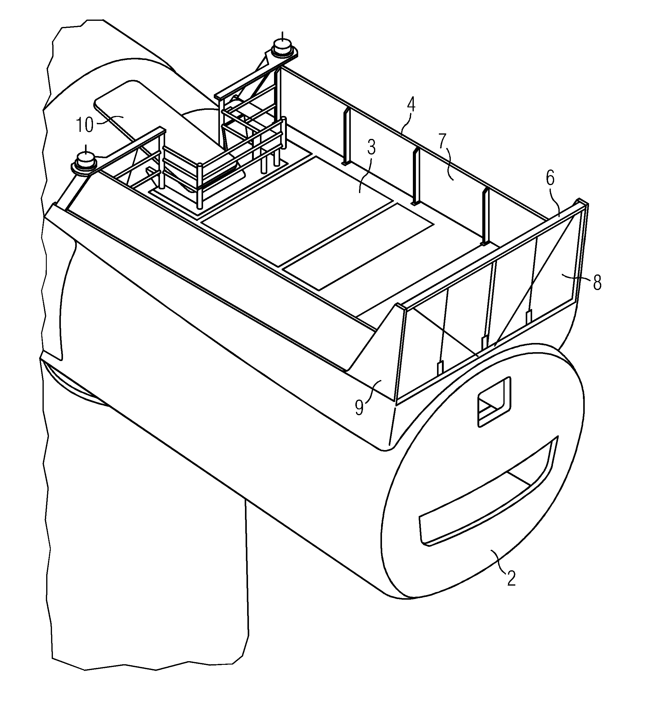
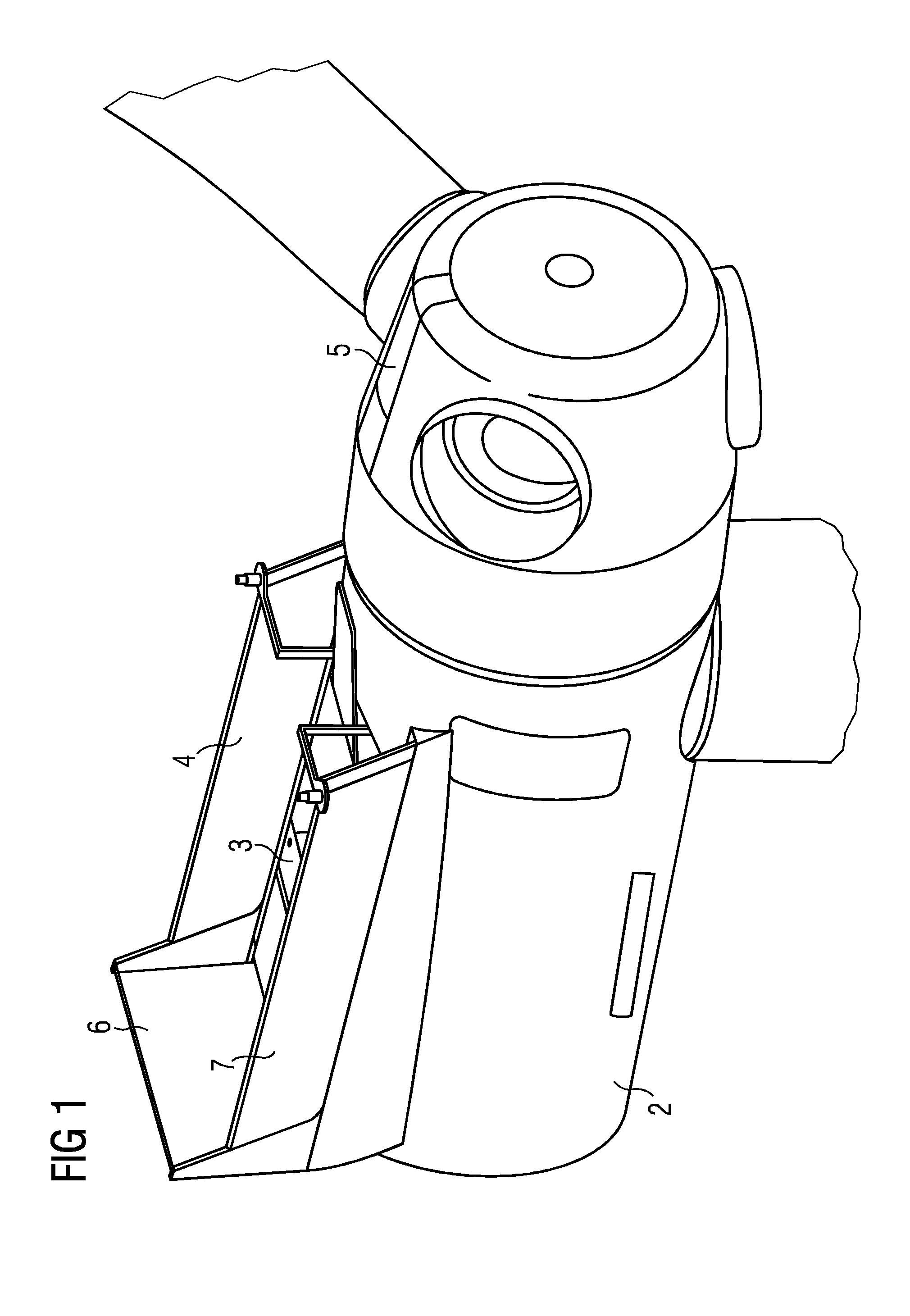
[0040]FIG. 1 shows a nacelle 2 of a wind turbine according to the invention. The nacelle 2 comprises a platform 3 that is surrounded by a barrier 4. The rear end of the platform is the part pointing away from the hub 5.

[0041]A cooling device 6 is provided on to of the nacelle 2. This cooling device 6 is an integral part of the rear part of the barrier 4. The barrier 4 surrounds the platform 3 at three sides. At the right and left side the barrier comprises a metal grid 7, so that the air flow of a hovering helicopter can move through the barrier 4.

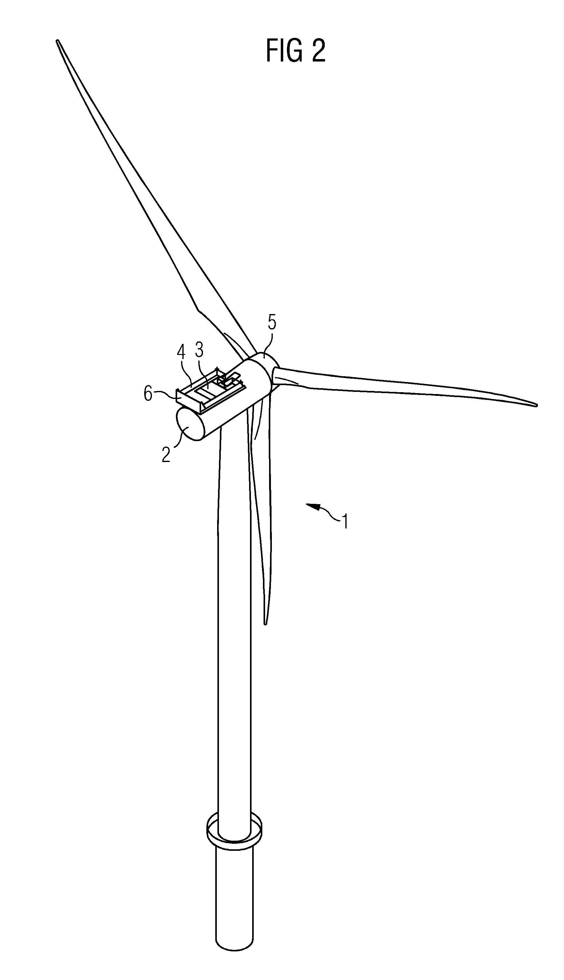
[0042]FIG. 2 shows a wind turbine 1 according to the invention. The wind turbine 1 is equipped with a platform 3 on top of the nacelle 2. The platform 3 is surrounded by a barrier 4.

[0043]The platform 3 can be approached by a helicopter. The platform 3 can be prepared to land on it with the helicopter. Or it is prepared to be used as a heli-drop zone or a heli-hoist platform to deliver or pick up equipment and personal to and from the plat...


PUM


Abstract

A cooling arrangement is provided for a wind turbine. The wind turbine has a nacelle. The cooling arrangement includes a cooling device and a platform. The cooling device is arranged on top of the nacelle and which is configured to remove heat of the wind turbine to the ambient air. The platform is located on top of the nacelle and which is configured to be approached by a helicopter. The platform includes a barrier, which surrounds at least a part of the platform. The barrier includes at least a part of the cooling device.

Description

CROSS REFERENCE TO RELATED APPLICATIONS[0001]This application claims priority of European Patent Office application No. 11165132.9 EP filed May 6, 2011. All of the applications are incorporated by reference herein in their entirety.FIELD OF INVENTION[0002]The invention relates to a cooling arrangement of a wind turbine.BACKGROUND OF INVENTION[0003]Electrical machinery produces heat and often needs a cooling system to remove the heat. The cooling system often comprises a cooling fluid that circulates in ducts or pipes. The cooling system further comprises a cooling arrangement as a heat sink. The cooling arrangement comprises a radiator and a support arrangement. The cooling fluid is then cooled by air flowing though the radiator. The radiator is therefore mounted in a way that the surrounding air can flow through the radiator.[0004]In the case of e.g. a wind turbine, the cooling system removes the heat from the generator or a bearing. The cooling fluid is cooled in the radiator. The...

Claims


Application Information

Patent Timeline
IPC IPC(8): F03D11/00F03D11/04
CPCF03D11/00F05B2240/14F05B2240/916F05B2260/20Y02E10/728Y02T50/675Y02E10/721Y02E10/726Y02E10/722F03D80/60Y02E10/72Y02T50/60
Inventor MUNK-HANSEN, THORKILNIELSEN, JACOB BLACH
Owner SIEMENS GAMESA RENEWABLE ENERGY AS
Learn More