
Electrical equipment having energy saving mode capable of shutting off supplying of voltage to primary power supply supplying circuit under no use thereof

a technology of energy saving mode and electrical equipment, which is applied in the direction of relays, contact mechanisms, transportation and packaging, etc., can solve the problems that the relay cannot be turned off, the relay cannot be used in all kinds of electrical equipment,

Inactive Publication Date: 2002-09-03
ALPS ALPINE CO LTD
View PDF12 Cites 14 Cited by
  • Summary
  • Abstract
  • Description
  • Claims
  • Application Information

AI Technical Summary

Benefits of technology

It is an object of the present invention to provide electrical equipment capable of solving the aforesaid problems, performing a pre-processing such as a security processing, for shutting off the power supply circuit at the electrical equipment, and concurrently setting a waiting electrical power in the primary circuit to zero.

Problems solved by technology

However, there was certain electrical equipment in many kinds of electrical equipment that the primary power supply supplying circuit must be turned OFF after performing a predetermined pre-processing before the primary power supply supplying circuit is turned OFF after performing a security processing and the like, so that there was a problem that the turning-OFF means of the relay means can not be used in all kinds of electrical equipment.
In addition, since the relay was sealed at its inner side by a sealing member, the relay could not be turned OFF directly in an enforced manner from outside, resulting in that when the power supply circuit of the electrical equipment produced a certain trouble and the circuit for the control system could not be controlled, the relay could not be turned OFF and a certain problem was found in view of its safety characteristic.

Method used


Image

  • Electrical equipment having energy saving mode capable of shutting off supplying of voltage to primary power supply supplying circuit under no use thereof
  • Electrical equipment having energy saving mode capable of shutting off supplying of voltage to primary power supply supplying circuit under no use thereof
  • Electrical equipment having energy saving mode capable of shutting off supplying of voltage to primary power supply supplying circuit under no use thereof

Examples


Embodiment Construction

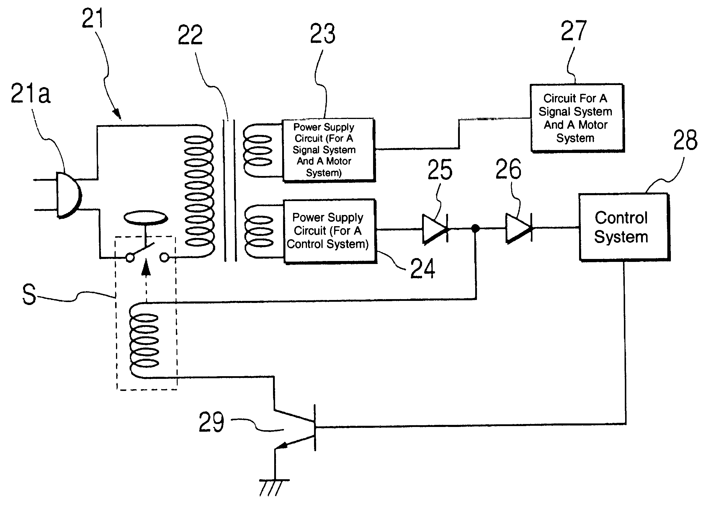
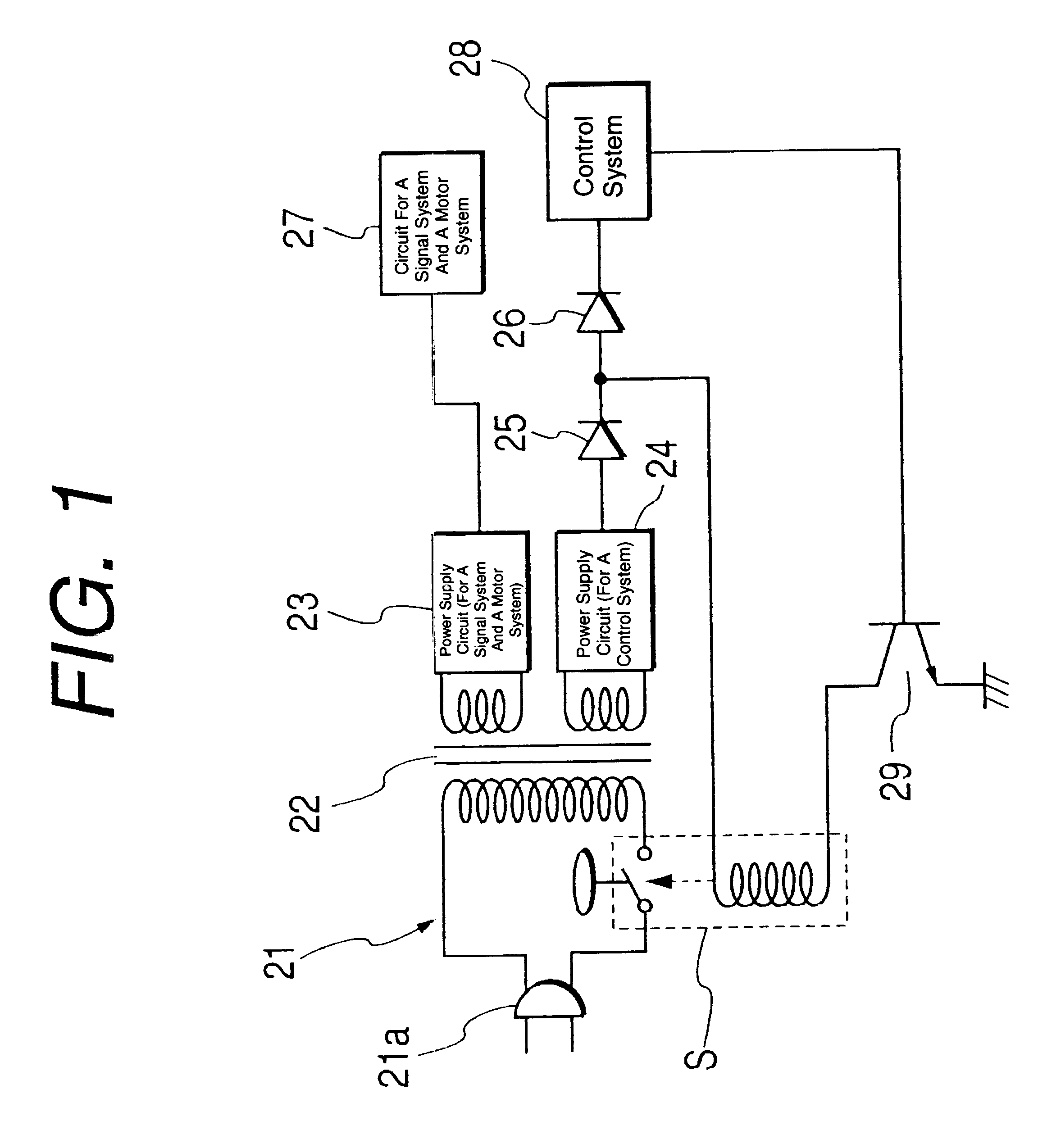
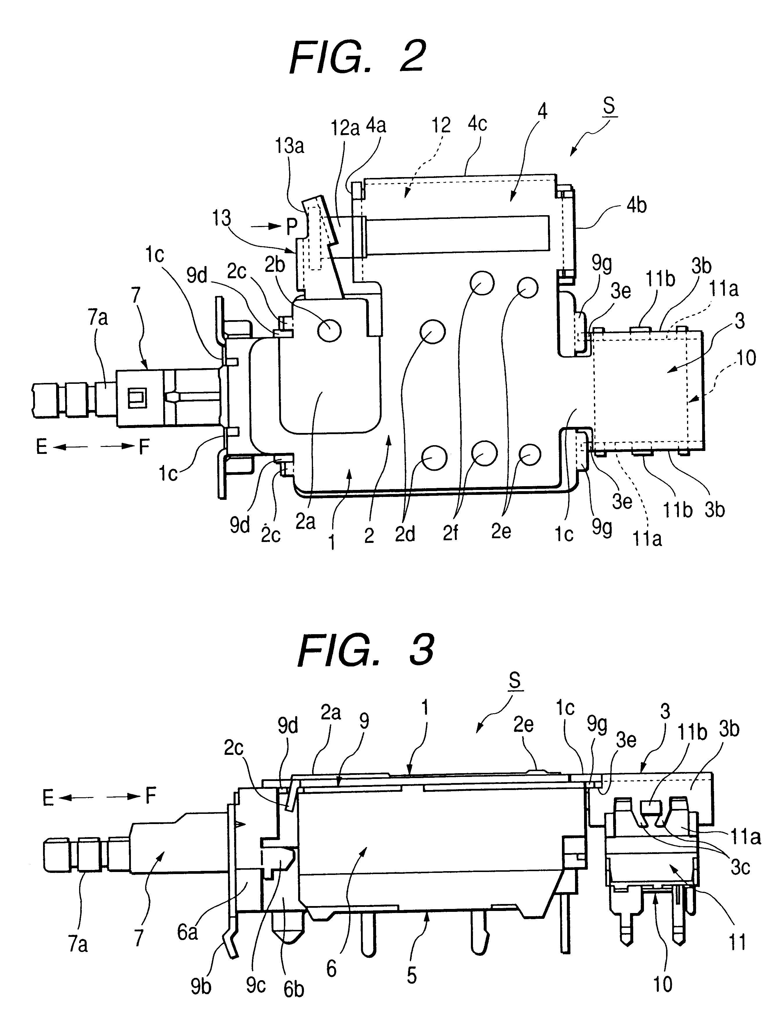
Referring now to the drawings, electrical equipment of the present invention will be described as follows. FIG. 1 is a substantial circuit diagram for showing a power supply control circuit in electrical equipment of the present invention. FIGS. 2 and 3 are a top plan view and a front elevational view for showing a switch device to be used in the circuit. FIGS. 4 and 5 are a top plan view and a front elevational view for showing a first switch of a switch device of the present invention. FIG. 6 is a substantial enlarged view for showing a switch device of the present invention. FIGS. 7 and 8 are schematic views for illustrating a cam bottom surface of a switch device of the present invention. FIGS. 9 and 10 are schematic views for illustrating an action of a lock member of a switch device of the present invention. FIG. 11 is a sectional view of a substantial part for illustrating a second switch of the present invention. FIG. 12 is a view for illustrating a relation between a contro...


PUM


Abstract

The electrical equipment of the present invention is operated such that the ON operating member for the primary power supply supplying circuit is manually operated, the switch device S is turned ON and when a supplying of electrical power for the primary power supply supplying circuit is shut off, the circuit for the control system is operated and upon performing a predetermined security processing, the driving source is driven, the OFF operating member is automatically operated, the switch device S is automatically turned OFF and supplying of an electrical power to the primary power supply supplying circuit is automatically shut off, so that it is possible to perform an appropriate processing before shutting off the primary power supply supplying circuit and thus it is also possible to provide electrical equipment showing a high safety characteristic.

Description

BACKGROUND OF THE INVENTION1. Field of the InventionThis invention relates to electrical equipment such as a television, VTR, a printer or a fan heater and the like, and more particularly, electrical equipment having an energy saving mode capable of shutting off of a supplying of a power supply voltage to the primary power supply supplying circuit under no use thereof.2. Description of the Related ArtReferring now to a fan heater, for example, the prior art electrical equipment, has a timer function connected to a power supply circuit, wherein due to a necessity for performing a combustion at a fan heater at a specified time even when the timer function is energized and the power supply is turned OFF, the primary power supply supplying circuit is always kept ON, consequently, a state in which a part of the secondary power supply supplying circuit is connected to the primary power supply supplying circuit is continued to be kept ON.Accordingly, in the case of the prior art fan heater...

Claims


Application Information

Patent Timeline
Patent Type & Authority Patents(United States)
IPC IPC(8): H01H13/56H01H13/50H02H3/12H01H9/54H02J3/00
CPCH01H13/568H02H3/12
Inventor MORI, TOSHIHARUTANABE, YOSHIOSOETA, KAORUGOTO, YOSHIMI
Owner ALPS ALPINE CO LTD
Learn More