Carburetor throttle and choke control mechanism
a technology of choke control mechanism and carburetor, which is applied in the direction of electrical control, heating types, separation processes, etc., can solve the problems of choke valve sometimes not being completely closed, failure in practice, and much to be desired
- Summary
- Abstract
- Description
- Claims
- Application Information
AI Technical Summary
Benefits of technology
Problems solved by technology
Method used
Image
Examples
first embodiment
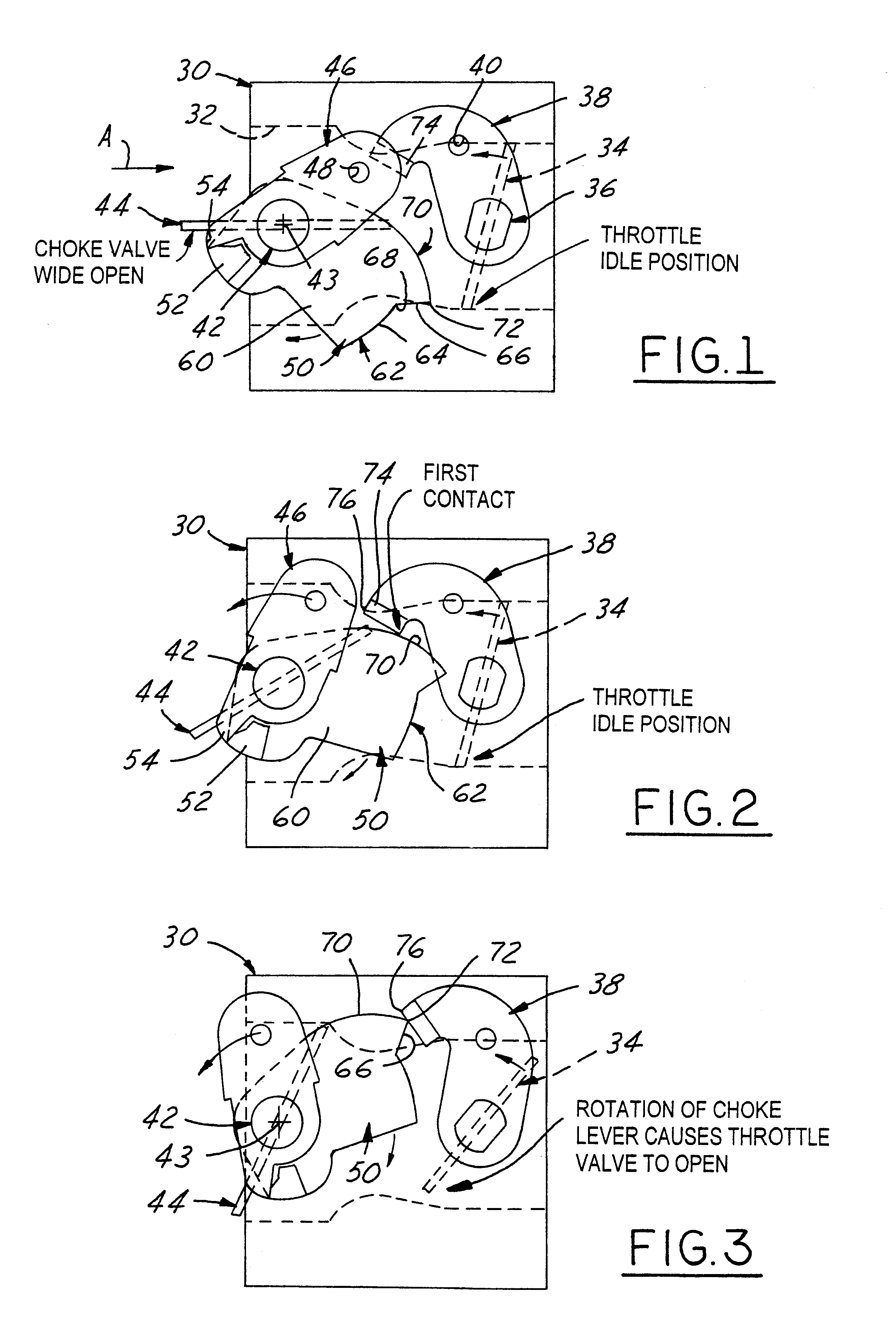
The first embodiment fast idle lever 50 as designed for one working embodiment is shown to engineering scale in the views of FIGS. 12, 13, 14 and 15, the configurations, angles and dimensions set forth therein being incorporated herein by reference to these views, the same being representative of the best mode of making and using the invention presently known to the inventors herein. However, it will be evident to those of ordinary skill in the art with the benefit of the foregoing description and drawings that contour variations may be readily made in the peripheral distal edge 62 of blade 60 and / or cam ramp 66 of fast idle lever 50 to suit the requirements of any particular FISS application, while retaining the novel mode of operation described hereinabove. Also, it is preferred that the fast idle lever 50 is constructed with a suitable material which has a low coefficient of friction such as acetal plastic (Delrin.RTM.).
Although the mode of operation of the foregoing configuratio...
second embodiment
The second embodiment of the invention as illustrated in FIGS. 9, 10 and 11, wherein the only change in component parts is that of the modified choke lever denoted 146 in these views. Choke lever 146 is constructed and mounted on choke shaft 42 in the same manner as choke lever 46 except for the modification of the pusher end of the choke lever. The pusher foot 54 of lever 46 is replaced by a flexible engagement hook portion 154 that is operable when the parts have been conditioned to the fast idle start position of FIG. 9 to pull and hold the choke valve closed when in its latched-up condition shown in FIG. 9. Preferably the choke lever hook 154 is molded as an integral portion of the choke lever 146 when the same is preferably made out of the material specified in the aforementioned co-pending Pattullo application, namely a resilient and flexible plastic material such as Delrin.RTM. acetal plastic. This is the material of the choke shaft disclosed in this co-pending application to...
third embodiment
As indicated previously, FIGS. 16, 17 and 18 are simplified diagrammatic views of a third embodiment "split linkage" carburetor equipped with a first embodiment type rigid choke shaft 42 and rigid choke lever split up into two separate components comprising a crank arm part 246 and a pusher foot part 346. The crank arm 246 is fixed to one end of choke shaft 42 on one side of the carburetor, whereas the pusher part 346 is fixed to the axially opposite end of choke shaft 42 on the other side of the carburetor. The remaining components of the FISS third embodiment system are the same as in the first embodiment system, and it will be seen that the mode of operation is also the same in both embodiments.
PUM
| Property | Measurement | Unit |
|---|---|---|
| choke valve angle | aaaaa | aaaaa |
| torsionally resilient | aaaaa | aaaaa |
| semi-resilient | aaaaa | aaaaa |
Abstract
Description
Claims
Application Information
 - R&D
- Intellectual Property
- Life Sciences
- Materials
- Tech Scout
- Unparalleled Data Quality
- Higher Quality Content
- 60% Fewer Hallucinations
Browse by: Latest US Patents, China's latest patents, Technical Efficacy Thesaurus, Application Domain, Technology Topic, Popular Technical Reports.
© 2025 PatSnap. All rights reserved.Legal|Privacy policy|Modern Slavery Act Transparency Statement|Sitemap|About US| Contact US: help@patsnap.com


