
Power compensation differential scanning calorimeter

a scanning calorimeter and power compensation technology, applied in the field of thermal analysis instruments, can solve the problems of general heat flow deviations and significant baseline heat flow deviations, and achieve the effect of improving baseline heat flow and improving dynamic respons

Inactive Publication Date: 2002-08-06
WATERS TECH CORP
View PDF23 Cites 53 Cited by
  • Summary
  • Abstract
  • Description
  • Claims
  • Application Information

AI Technical Summary

Benefits of technology

A further object of the present invention is to provide a power compensation DSC with improved baseline heat flow and improved dynamic response.

Problems solved by technology

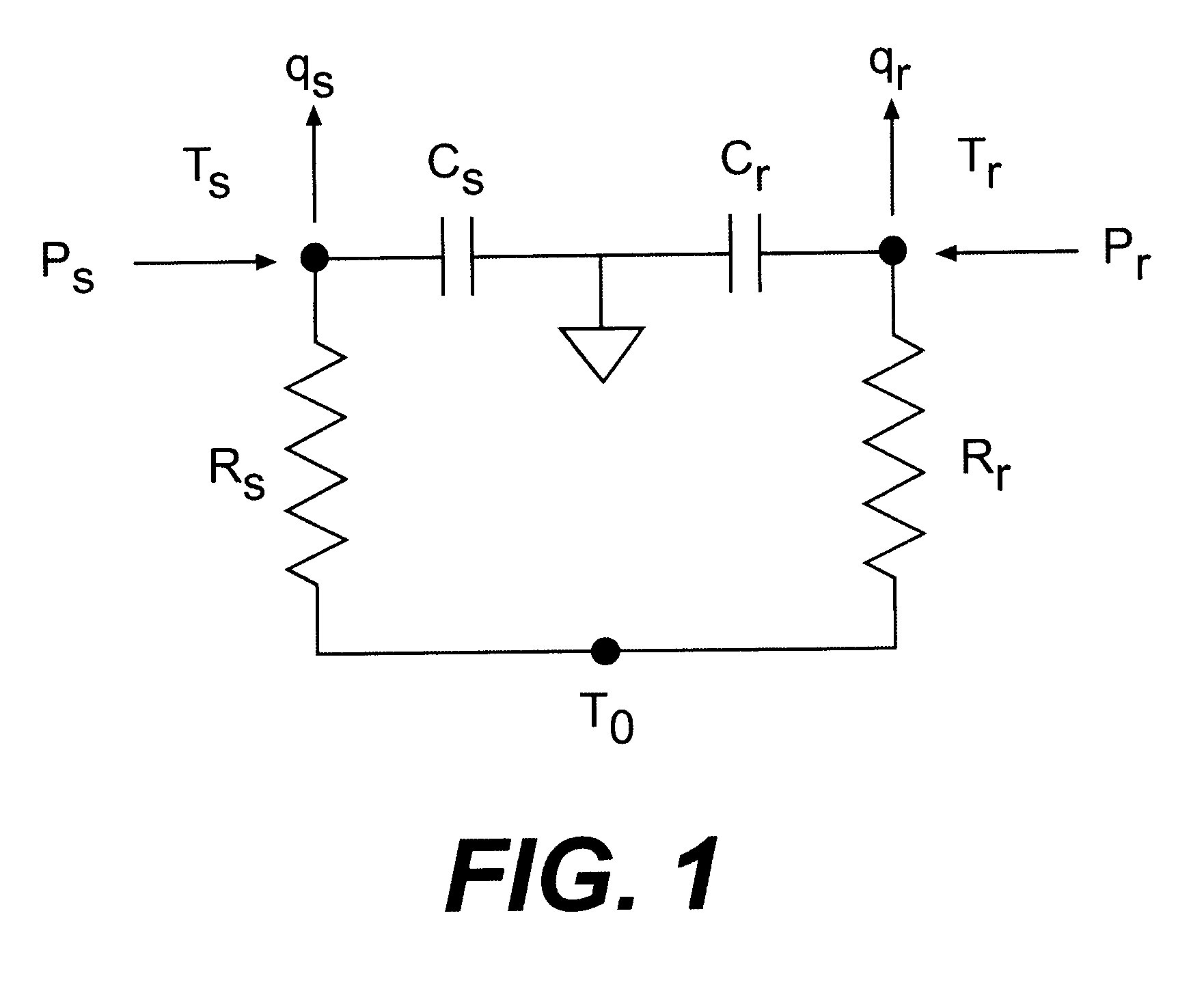
In reality, because of manufacturing imprecision and the variability of the heat exchange processes between the sample holder and the isothermal enclosure and between the reference holder and the isothermal enclosure, imbalances generally exist.
These imbalances contribute to baseline heat flow deviations that may be significant.

Method used


Image

  • Power compensation differential scanning calorimeter
  • Power compensation differential scanning calorimeter
  • Power compensation differential scanning calorimeter

Examples


Embodiment Construction

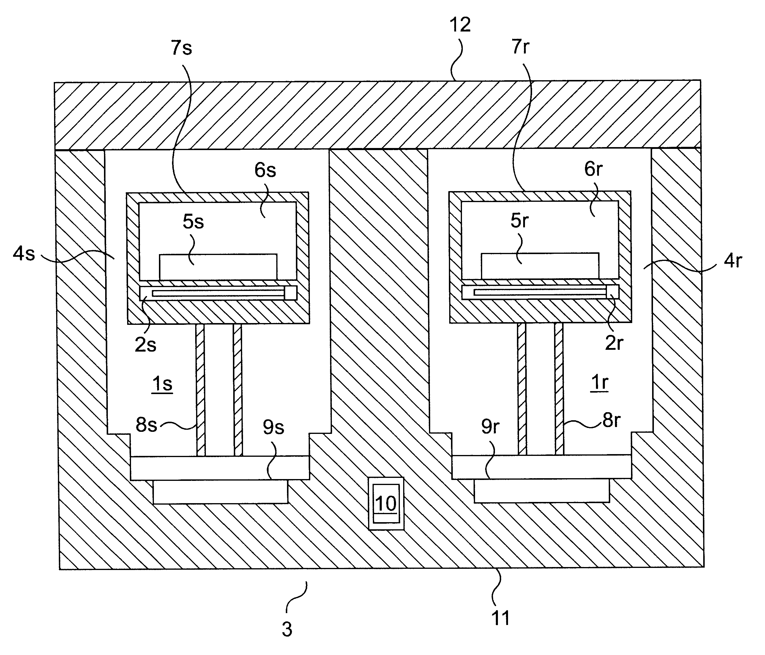
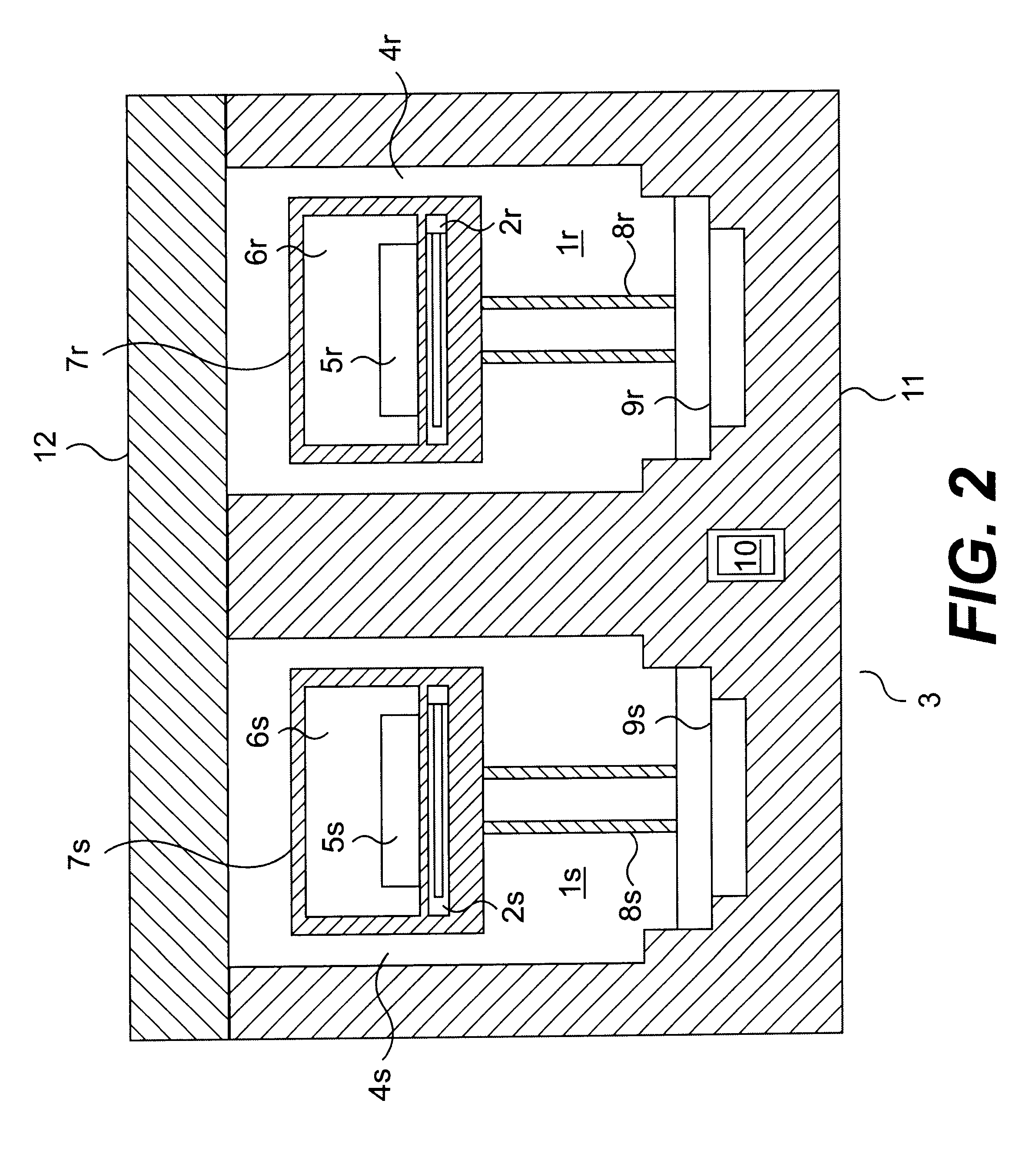
FIG. 2 is a schematic diagram of a cross-sectional view of a power compensation DSC cell of the present invention. The DSC cell comprises a sample holder assembly is and a reference holder assembly 1r installed in an isothermal enclosure 3. Overall, the sample and reference holder assemblies are manufactured to be as identical as possible. Sample holder 1s has a body 4s in which are embedded a temperature detector 2s, and a heating element (not shown in FIG. 2). A sample in a sample pan 5s is inserted in the cavity 6s of the sample holder, which is closed by a lid 7s. The body of the sample holder 4s is supported by thermal resistor 8s, which is attached to flange 9s. The thermal resistor is the principal path for heat exchange between the sample holder and the isothermal enclosure and allows the sample holder to be heated to temperatures much higher than the isothermal enclosure by applying a modest quantity of heater power. Thermal resistor 8s is a tubular member with a small cros...


PUM


Abstract

A power compensation differential scanning calorimeter that uses one absolute temperature measurement, two differential temperature measurements, a differential power measurement, and a five-term heat flow equation to measure the sample heat flow. The calorimeter is calibrated by running two sequential calibration experiments. In a preferred embodiment, the first calibration experiment uses empty sample and reference pans, and the second calibration experiment uses sapphire specimens in the sample and reference holders. In an alternate embodiment, sapphire calibration specimens are used in both the first and second calibration experiments.

Description

1. Field of the InventionThe present invention relates to a thermal analysis instrument, and more particularly, to a power compensation differential scanning calorimeter.2. Background of the InventionDifferential scanning calorimeters (DSCs) measure the flow of heat to a sample to be analyzed as a function of time and temperature. DSCs are described in "Differential Scanning Calorimetry: an Introduction for Practitioners," G. Hohne, W. Hemminger and H. J. Flammersheim (Springer-Verlag: 1996) and "Thermal Analysis," Bernhard Wunderlich (Academic Press, 1990).Power compensation DSCs are a specific type of DSC that measure the difference in power supplied to the sample compared to the reference throughout the analysis. Power compensation DSCs are described in "A Differential Scanning Calorimeter for Quantitative Differential Thermal Analysis", E. S. Watson and M. J. O'Neill, Analytical Chemistry Vol. 36, No 7, pp. 1233-1238 (June 1964), "The Analysis of a Temperature-Controlled Scannin...

Claims


Application Information

Patent Timeline
IPC IPC(8): G01N25/20G01N25/48G01K17/00G01K17/04
CPCG01K17/00G01K17/04G01N25/4833G01N25/4866
Inventor DANLEY, ROBERT L.
Owner WATERS TECH CORP
Learn More