
Device for introducing CO2 snow into containers in order to cool the content of said containers or to cool the containers themselves

Inactive Publication Date: 2002-08-06
CRAFT TECH
View PDF10 Cites 2 Cited by
  • Summary
  • Abstract
  • Description
  • Claims
  • Application Information

AI Technical Summary

Benefits of technology

The invention is thus based on the object of developing the known apparatus to the effect that already existing devices can be easily retrofitted with a dough or, respectively, container cooling.
Beneficially, the snow tube is widened at the CO.sub.2 snow delivery side. A more uniform output of the CO.sub.2 snow into the container is thus assured.
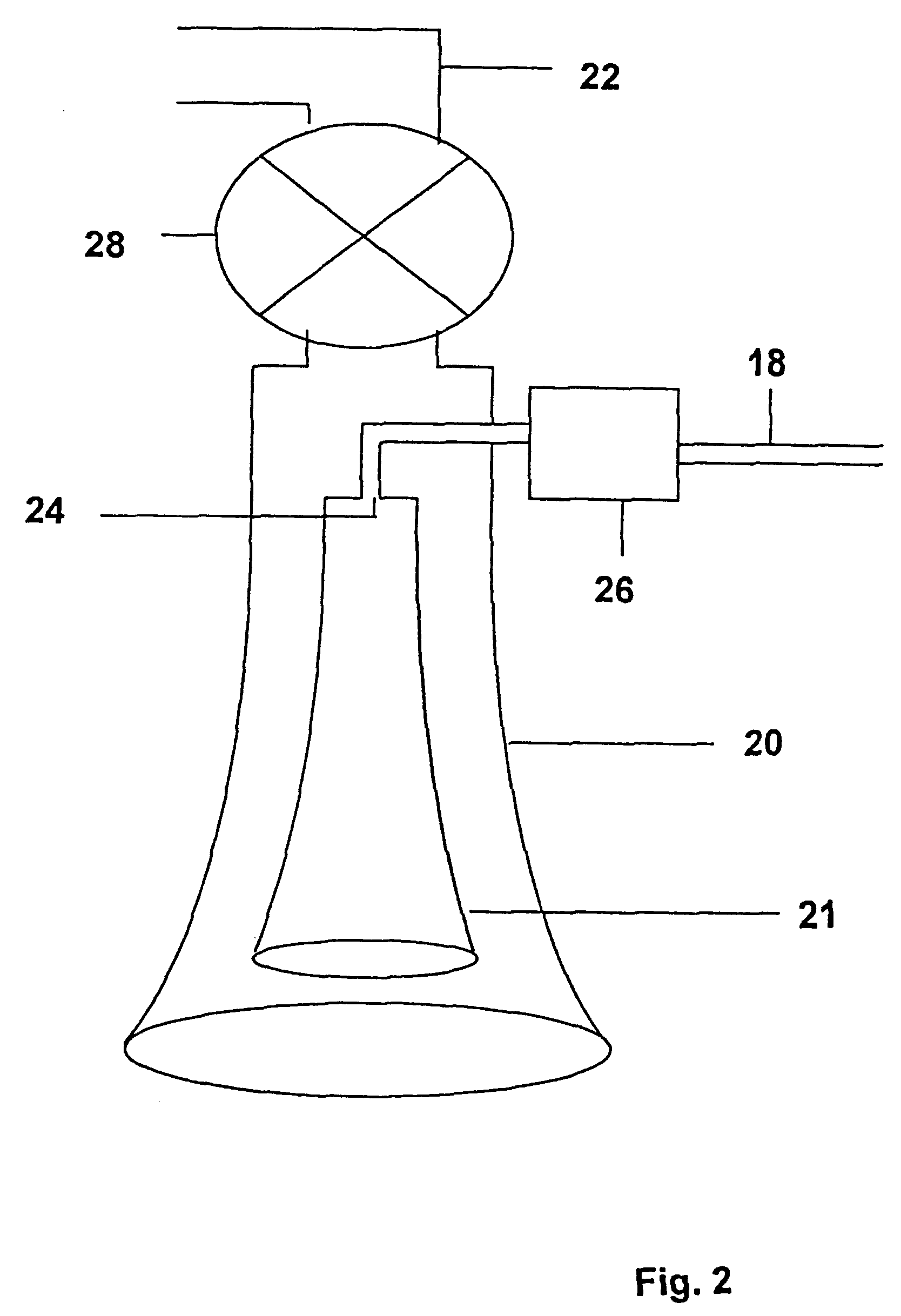
The invention is based on the surprising perception that the concentric arrangement of the snow tube and the surrounding outer tube of the separating means results merely in a double tube and, thus, a structural intervention for passing the double tube through need only be undertaken at one location of the container cover for retrofitting existing devices with the dough or container cooling. Over and above this, the snow tube that is shorter compared to the outer tube enables an extraction of the CO.sub.2 not converted into CO.sub.2 snow before the CO.sub.2 gas enters into the container at all, which enables a better monitoring and setting of the partial oxygen pressure in the head space of the container and, further, prevents a displacement of the oxygen as well as an introduction of the CO.sub.2 gas into the product located in the container as well as contact therewith. Due to the cyclone effect, moreover, the inventive apparatus exhibits an extremely high CO.sub.2 snow generating efficiency that nearly corresponds to the theoretical efficiency of 60%. The CO.sub.2 gas extraction means, in combination with the outer tube, can also be employed after the CO.sub.2 snow injection phase to extract the CO.sub.2 gas subsequently formed with the CO.sub.2 snow. The inventive apparatus thus enables an especially good cooling of the reaction processes with the cold content of the CO.sub.2 snow without the product to be cooled coming into contact with the CO.sub.2 gas to any noteworthy extent and being thus damages.
3. Fruit and vegetable processing: peeled apples or peeled potatoes but also salads (iceberg salad, etc.) can be preserved by water emersion baths (low-pressure container) specifically saturated with the CO.sub.2 snow. As a result thereof, an employment of preservatives (sulfites, etc.) can be avoided. The objective is, on the one hand, to introduce .gtoreq.7.0 g CO.sub.2 / kg water and, on the other hand, to exploit the cooling effect. The high CO.sub.2 concentration enables both anti-microbial effects (reduction in the number of germs) as well as the minimization of enzymatic processes ("enzymatic browning" due to phenoloxidases) due to O.sub.2 displacement, and the like. The necessary CO.sub.2 concentration given simultaneous cooling effect can be achieved by dry ice (CO.sub.2 snow). The extraction of the CO.sub.2 gas is therefore also required for this process.
4. Grain mashes: in a malt house, grain is caused to germinate in germination boxes or the like at high water contents and elevated temperature (approximately 5 through 7 days). Cooling these mashes down to further-processing or, respectively, storing temperature dare not change the water content of the mashes and should be as fast as possible (due to the microbial risks) but without any CO.sub.2 gas (in order to avoid anaerobic processes for avoiding disadvantageous solubilization or extraction processes as well that occur due to the CO.sub.2 gas in solution). In a similar application, what are referred to as "brew batches" (cooked grain) in a bakery can be very rapidly cooled to further-processing or, respectively, storing temperature without changing the dough yield (water content) and without introduction of the CO.sub.2 gas.
The inventive apparatus can also be of great assistance in maintaining the cooling chain when transporting food stuffs and other sensitive materials. With the assistance of non-stationary apparatus, for example, a suitable insulating container can be very easily "snowed" with the CO.sub.2 snow. When this is carried out at the upper part of the container, a uniform distribution of the snow from top to bottom occurs, and this causes a very uniform distribution on the repackaged food stuffs (cartons, etc.). As a result thereof, the desired transport or intermediate storing temperature of, for example, 18.degree. C. can be maintained over a long time (for example eight hours). Here, too, the active removal of the CO.sub.2 gas arising "in statu nasceni" is necessary in order to assure adequate worker protection and working security (the enrichment of CO.sub.2 gas in the environment is intolerable for reasons of worker safety). When unpackaged food stuffs are to be cooled and transported in the insulated container (for example, open cream products, bakery products with unbaked filling, baked goods, sausages, etc.), then snowing with dry ice can ensue. CO.sub.2 gas (water as well) is to be avoided here, first in order to prevent a quality change of the product (taste, color etc.) and, on the other hand, in order to adhere to work protection and work safety.

Problems solved by technology

This cooling method, however, has a physical limit since the proportion of water in the product is also raised due to intensified cooling.
The known apparatus cited at the outset exhibits the disadvantage that devices that are already present such as, for example, dough agitators can be refitted with a dough or, respectively, container cooling only with relatively great structural outlay.

Method used


Image

  • Device for introducing CO2 snow into containers in order to cool the content of said containers or to cool the containers themselves
  • Device for introducing CO2 snow into containers in order to cool the content of said containers or to cool the containers themselves
  • Device for introducing CO2 snow into containers in order to cool the content of said containers or to cool the containers themselves

Examples


Embodiment Construction

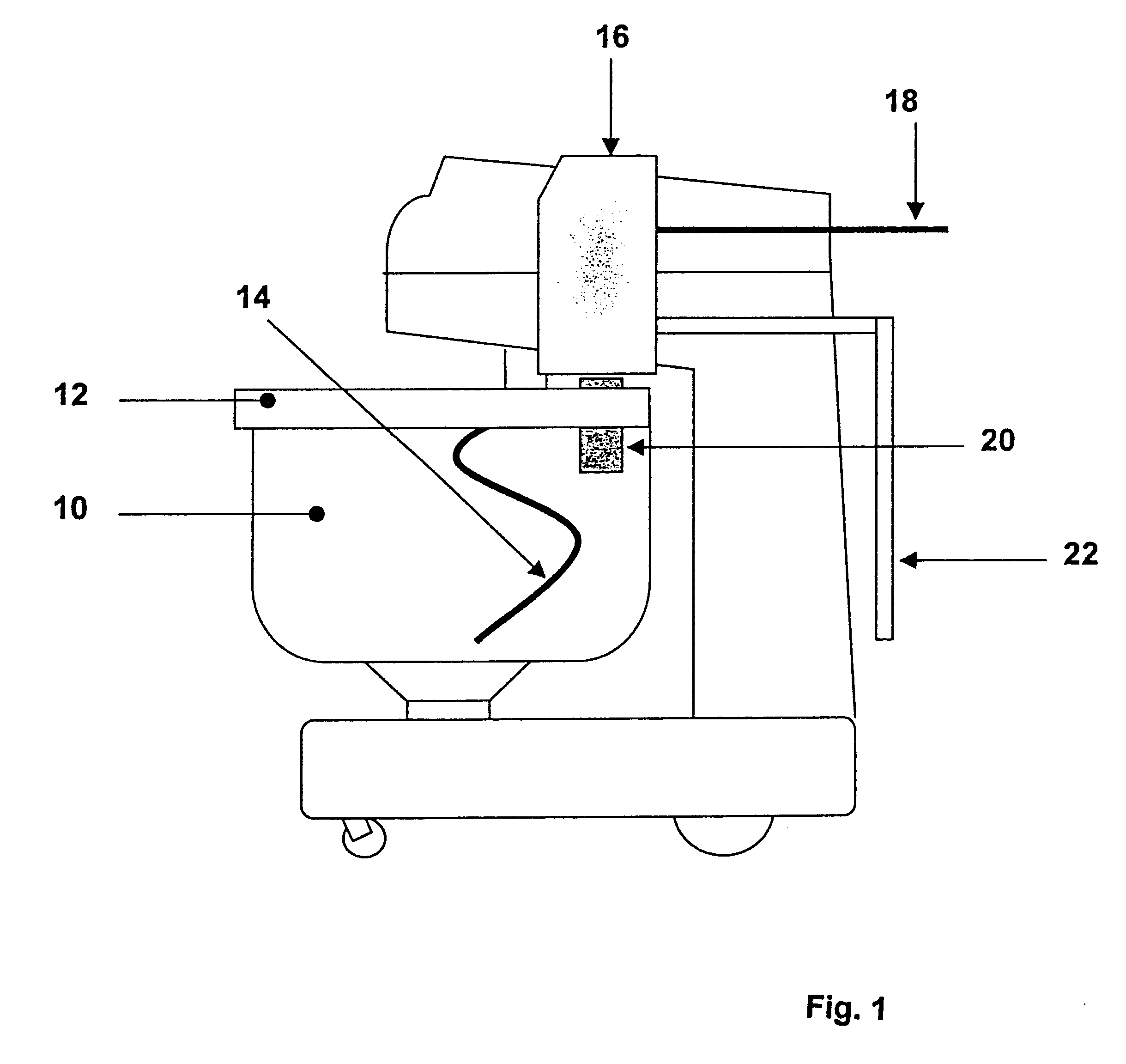
FIG. 1 shows a dough kneading machine with a kneading container 10, a container cover 12 and a kneading arm 14. A specific embodiment of the inventive apparatus 16 is located next to the kneading arm 14 for introducing a CO.sub.2 snow into the kneading container 10 for cooling a bread dough (not shown) situated in the kneading container 10. The inventive apparatus 16 comprises a delivery conduit 18 for delivering a liquid CO.sub.2, an outer tube 20 with an inner snow tube (not shown) for injecting the CO.sub.2 snow produced in the apparatus 16 into the kneading container 10 as well as an exhaust gas conduit 22 for eliminating the CO.sub.2 gas.

FIG. 2 shows details of the inventive apparatus 16 of FIG. 1. A coaxially arranged snow tube 21 is located in the outer tube 20, the upper end thereof being 20 connected with the supply line 18 via a nozzle 24 and a solenoid or solenoid valve 26. The outer tube 20 and the snow tube 21 are comically fashioned, whereby the cross-sections of the o...


PUM


Abstract

Apparatus for the introduction of CO.sub.2 snow into containers for cooling the container contents or the container, comprises a CO.sub.2 snow generating device for generating the CO.sub.2 snow, a CO.sub.2 snow injection device connected to the CO.sub.2 snow generating means and having a snow tube for injecting the generated CO.sub.2 snow into the container, a the CO.sub.2 gas separating arrangement for separating CO.sub.2 gas and CO.sub.2 snow in the region of the snow tube, and the CO.sub.2 gas extraction arrangement for extracting separated the CO.sub.2 gas, the CO.sub.2 gas separating arrangement comprises an outer tube surrounding the snow tube and arranged coaxially with the outer tube projecting beyond the snow tubed in longitudinal direction thereof at the CO.sub.2 snow delivery side of the snow tube and being connected to the CO.sub.2 gas extraction arrangement in the region of the opposite side.

Description

BACKGROUND OF THE INVENTIONThe present invention is directed to an apparatus for introducing CO.sub.2 snow into containers for cooling the container contents or the container. The apparatus has a CO.sub.2 snow-generating means for generating CO.sub.2 snow, a CO.sub.2 snow injection means connected to the CO.sub.2 snow generating means a snow tube for the injection of the generated CO.sub.2 snow into the container, a CO.sub.2 gas separating means for the separation of CO.sub.2 gas and CO.sub.2 snow in the region of the snow tube and a CO.sub.2 gas extraction means for extracting separated CO.sub.2 gas. What is to be understood here by generating CO.sub.2 snow is that conditions are created whereat CO.sub.2 snow arises.In many technical processes, the product to be processed must have its temperature maintained within a specific range in order to avoid damage to or poorer workability of the product. Due to the introduction of mechanical energy, for example in the form of mixing or hom...

Claims


Application Information

Patent Timeline
IPC IPC(8): F25D3/12F25D3/00
CPCF25D3/12
Inventor LOSCHE, KLAUSDIRKSEN, GERHARDWIESMANN, RALFSIKKEN, DIRK
Owner CRAFT TECH
Learn More