Eureka AIR delivers breakthrough ideas for toughest innovation challenges, trusted by R&D personnel around the world.

Impact absorbing composites and their production

a composite and impact absorption technology, applied in the direction of pedestrian/occupant safety arrangements, transportation and packaging, vehicular safety arrangements, etc., can solve the problems of minimal protection, interference with design, and bottom out, and achieve efficient impact absorption, efficient impact absorption, and efficient impact absorption

Inactive Publication Date: 2002-07-30
DONZIS BYRON A
View PDF50 Cites 92 Cited by
  • Summary
  • Abstract
  • Description
  • Claims
  • Application Information

AI Technical Summary

Benefits of technology

An improved impact absorbing composite has now been found. This composite is capable of dispersing and absorbing impacting forces with high efficiency. The composite is characterized by a structure including a flexible plastic wall (enclosure) defining an internal cavity. This flexible enclosure is made of a material that is generally impermeable to air and is capable of having its internal pressure changed. The internal cavity of the enclosure is filled with a foam core. This core is held in place by the cavity walls. Importantly, the core is intimately adhered (glued, bonded or the like) on substantially all of its external surfaces to the internal surface of the cavity. In preferred embodiments, the wall and the core are prestressed by one another. That is, the core presses out against the wall and the wall pushes in against the core. The intimate adherent contact between the foam core and the outer wall gives rise to an unexpected degree of product integrity and unexpectedly superior impact absorbing capabilities.
The composites of this invention are characterized by being easily formed in compound curve forms, by being very light weight and by being hygienic. They are further characterized by being adjustable in pressure, and thus in impact cushioning capacity. This permits them to serve in a wide range of applications with widely variable impacts.

Problems solved by technology

These designs have the disadvantage that they often "bottom out" or fully compress on severe impacts of the type regularly encountered during use such as in athletic equipment or in vehicle interiors and thus provide minimal protection.
When made thicker to avoid this problem, they become cumbersome and can interfere with the design of the article being padded, and in the case of athletic equipment can interfere with the wearer's freedom and performance.
While effective as shock absorbers, these devices can have the failing of ballooning or otherwise expanding in one region when another region is being compressed.
This can lead to discomfort or at minimum give an unnatural or unstable feel to the user.
In the case of footwear, this problem can lead to an unstable foot plant with increased opportunity for injury.
Another issue with this type of pad has related to problems in forming shapes based on compound curve and to retaining structural integrity with the above-described ballooning.

Method used


Image

  • Impact absorbing composites and their production
  • Impact absorbing composites and their production
  • Impact absorbing composites and their production

Examples


Embodiment Construction

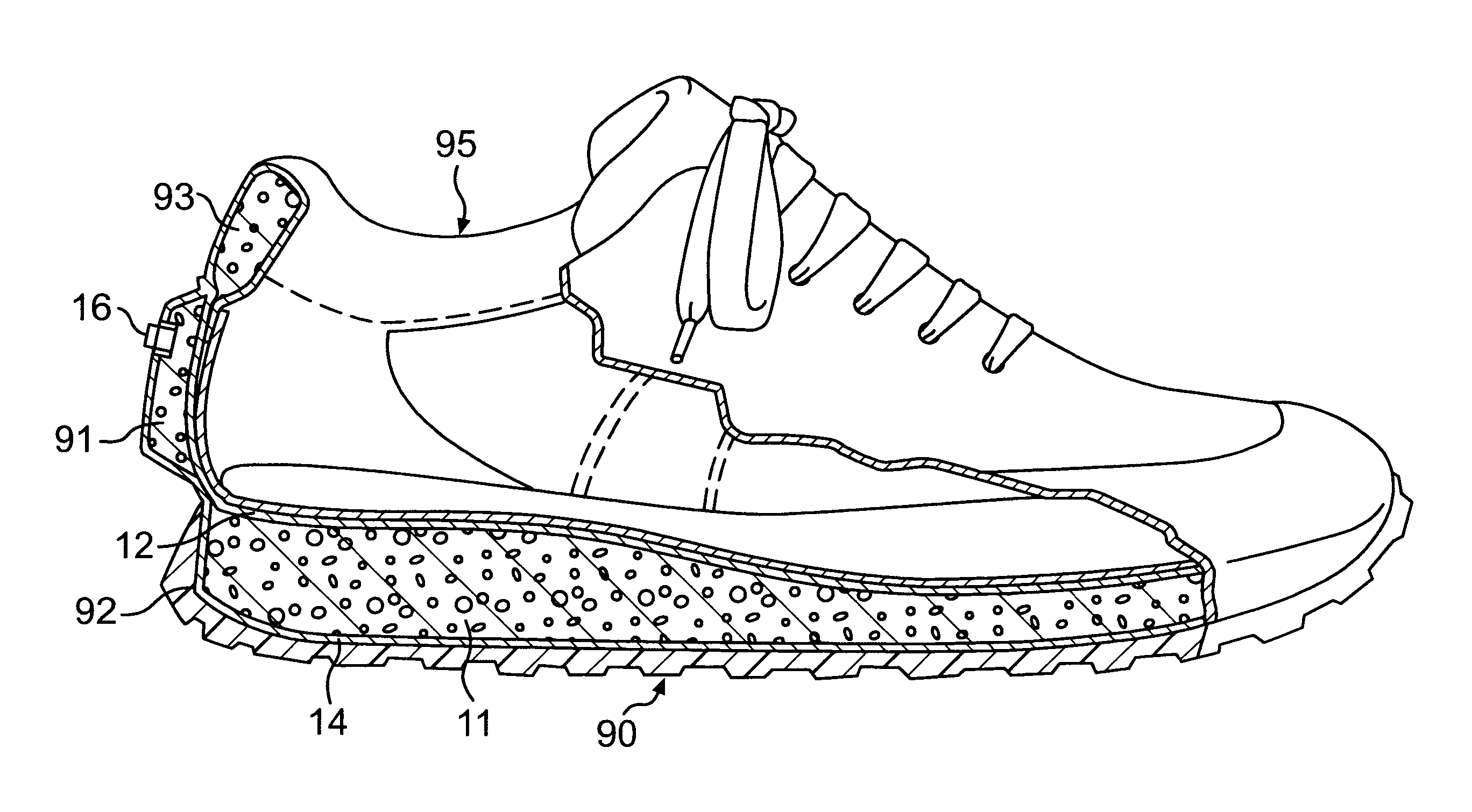
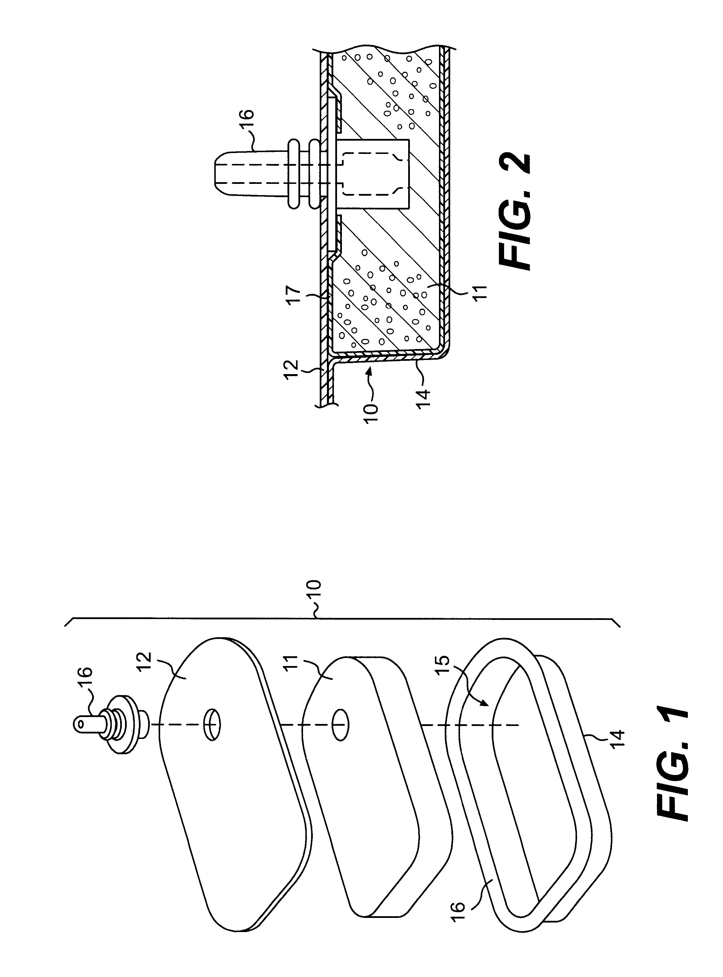
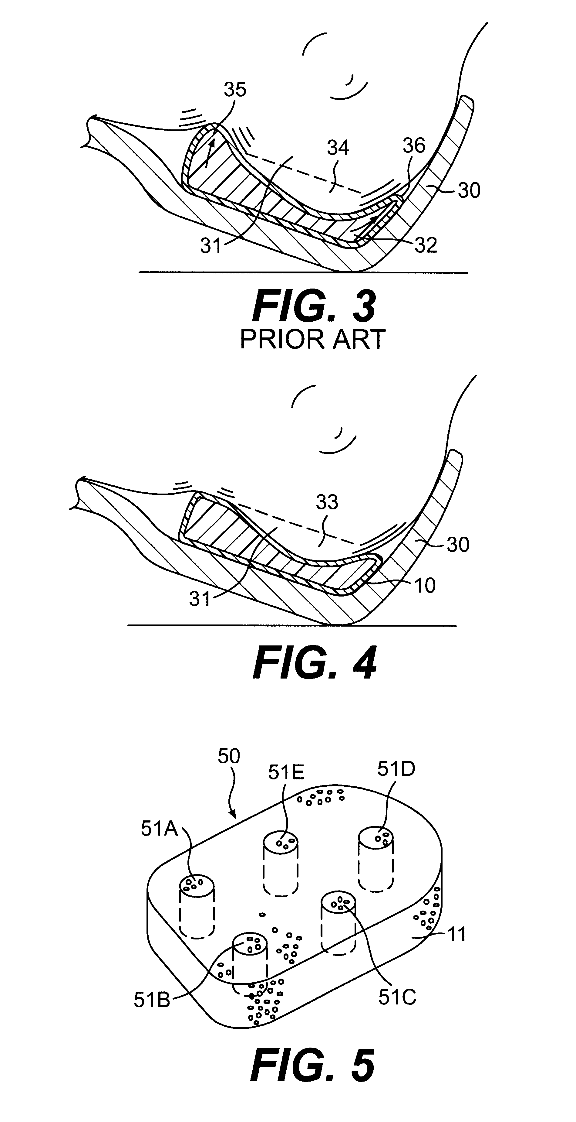
Referring to FIGS. 1 and 2 in more detail, these figures illustrate an impact absorber 10. Impact absorber 10 includes a foam core 11 and top and bottom wall sections 12 and 14 which when joined define a cavity 15. A layer of adhesive 16 is present between essentially all of the inner surface of cavity 15 and the outer surface of foam core 11. This layer is shown on core 11 but could as well be on the inside surface of the wall or on both the core and the wall as desired. When wall sections 12 and 14 are joined, the cavity which they define is pressure tight. It is possible to equip the impact absorber with a valve or fitting such as valve 16. Valve 16 is a "Halkey-Roberts" type urethane valve which is shown in FIG. 1 in its pre-assembly form. After incorporation, the top end of valve 16 is cut off flush with the surface of the shock absorber as shown in FIG. 2. Any equivalent form of valve or pressure control aperture can be used, if desired. This valve allows the pressure in the i...


PUM

PropertyMeasurementUnit
thicknessesaaaaaaaaaa

Abstract

An improved composite for absorbing and dispersing impacting forces is disclosed. The composite includes a flexible plastic enclosure defining an internal cavity. The flexible enclosure is generally impermeable to air and capable of having its internal pressure changed. The composite further includes a foam core filling the cavity and retained within the cavity and adhered on substantially all of its external surface to the internal surface of the cavity. The cavity can be pressurized for higher impact absorbance. Methods for fabricating the composites are disclosed, as well.

Description

1. Field of the InventionThis invention relates to improved impact absorbing compressible composites. These composites can be shaped into smooth compound curves and find application wherever high efficiency impact absorption is called for such as in athletic wear, in seating systems, in vehicle interior padding materials and the like.2. Background InformationThere is a well-recognized need for high performance materials for spreading or absorbing impacts. In recent years, athletes, athletic equipment manufacturers and sports medicine professionals have recognized the need for improved impact absorbing materials in athletic equipment. These materials find application as heel pads and foot sole pads in shoes to absorb the shock of foot strike and as cushioning points under football or hockey pads such as shoulder pads, thigh pads, hip pads and the like to name but a few typical applications. Similar needs may be found in seating systems and in vehicle interiors, to name but a few repr...

Claims


Application Information

Patent Timeline
Patent Type & Authority Patents(United States)
IPC IPC(8): A41D31/00B32B3/26B60R21/04B60R21/045F16F1/37F16F1/36
CPCA41D31/005B32B3/26B60R21/045F16F1/37A41D31/285
Inventor DONZIS, BYRON A.
Owner DONZIS BYRON A
Why Eureka
Eureka Blog
Learn More