
Probe and test socket assembly

a technology of socket assembly and probe, which is applied in the direction of electrical testing, measurement devices, instruments, etc., can solve the problems of high manufacturing cost, high rejection rate, and high cost of scrapping finished objects, and achieve low cost and high degree of accuracy

Inactive Publication Date: 2002-07-23
SMITHS INTERCONNECT AMERICAS INC
View PDF7 Cites 30 Cited by
  • Summary
  • Abstract
  • Description
  • Claims
  • Application Information

AI Technical Summary

Benefits of technology

to provide such a probe which can be manufactured with a high degree of accuracy and low cost; and

Problems solved by technology

Particularly with complex and expensive IC's, reliability of the test readings is of critical importance, for such DUT's are normally costly and failing a DUT because of test socket and probe failure can lead to a needlessly high rejection rate which increases the cost of manufacture.
If the IC then fails, scrapping the finished article is extremely expensive both in terms of material and time costs.
An integrated circuit of complexity with densely packed pad contacts is expensive, making accuracy and reliability of the test equipment critical.
The test equipment is even more expensive and a test socket densely packed with test probes more expensive yet.
Because of the costs involved, these devices must be reliable and have long life.
Such probes are extremely difficult to manufacture, as they typically consist of a barrel, a coiled spring within the barrel and extensible plunger extending from the barrel and biased to an extended position by the coil spring.
Crimping requires an extra step of manufacture and is difficult in an item so small.
The probe is designed for maximum electrical contact, leading to extremely low resistance and does not have a crimp or other conventional connecting means.
The probe provides extremely low and consistent electrical resistance.

Method used


Image

  • Probe and test socket assembly
  • Probe and test socket assembly
  • Probe and test socket assembly

Examples


Embodiment Construction

Detailed embodiments of the invention are disclosed herein; however, it is to be understood that the disclosed embodiments are merely exemplary of the invention which may be embodied in various forms. Therefore, specific structural and functional details disclosed herein are not to be interpreted as limiting, but merely as a basis for teaching one skilled in the art to variously employ the present invention in any appropriately detailed form, and as a basis for the claims.

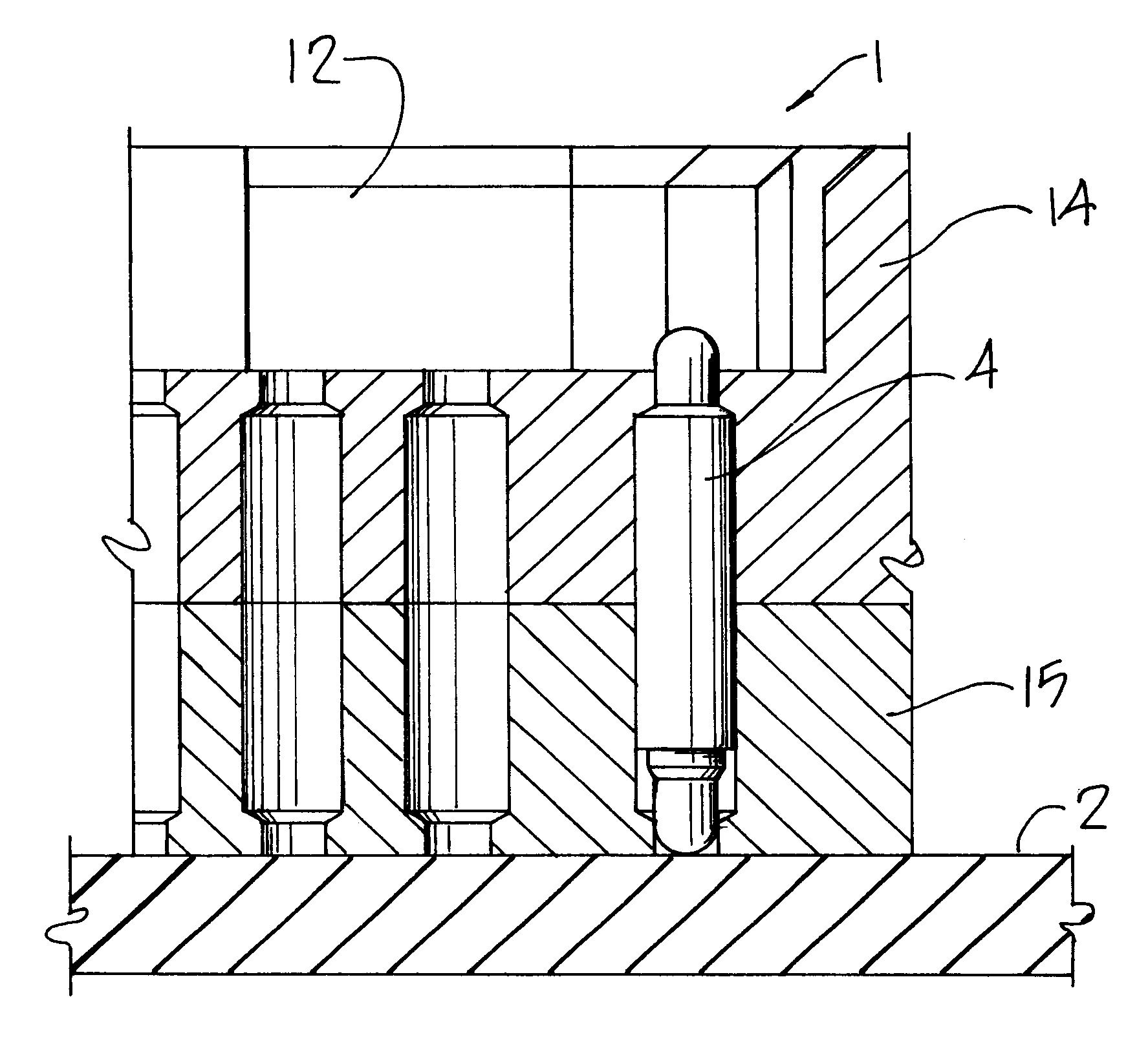
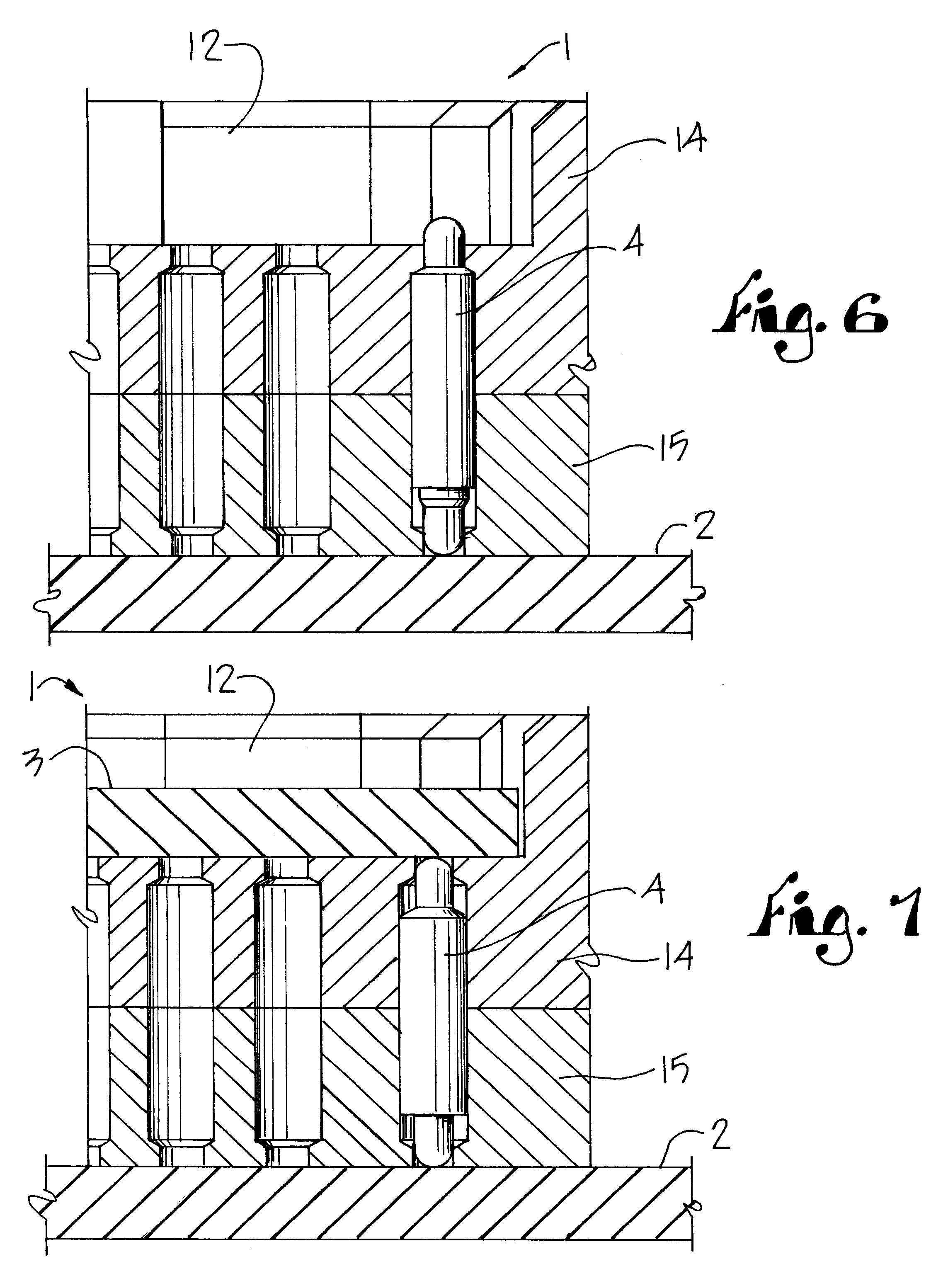
The reference numeral one, FIG. 1, generally indicates a test socket which is mounted upon a circuit board 2 which is part of an automated testing apparatus (not shown). The automated testing apparatus is computer-controlled to provide a sequence of electrical impulses through the circuit board 2, the test socket 1 and into an integrated circuit chip 3, which constitutes the device under test (DUT). The test socket I contains a densely packed array of extremely small diameter probes 4. These probes 4 each contain a...


PUM


Abstract

A probe and test socket assembly wherein spring biased plunger probes of extraordinarily small diameter, such as 0.02 inch, are densely packed into a test socket for testing of integrated circuit chips. The socket is constructed in upper and lower halves with bores to receive the probes. To manufacture probes of such small diameter and to provide minimal and constant electrical resistance, the plungers and barrel of the probes are not crimped or otherwise secured together. The configuration of the socket bore walls in combination with the probe maintains the probe plunger and barrel together. The assembly is particularly useful in densely packed arrays of extremely fine diameter probes for testing densely packed test sites.

Description

This invention relates to spring biased electrical contact probes in general and specifically to such probes that are of extremely small size and used in densely packed electrical test sockets.Test sockets are used in the electrical circuit test industry as an interface between a test circuit board and the device under test, commonly called a DUT. Test sockets are normally used for a DUT that has relatively densely packed contact points. Such a device could be an integrated circuit chip, commonly called an IC. The test socket is configured to receive a particular configuration of IC. Electrical test spring contact probes in the well of the test socket extend to the other side of the socket and contact a circuit board on which the test socket is mounted. The test sockets and their loaded probes establish an electrical contact path between the DUT and the circuit board.Particularly with complex and expensive IC's, reliability of the test readings is of critical importance, for such DU...

Claims


Application Information

Patent Timeline
Patent Type & Authority Patents(United States)
IPC IPC(8): G01R1/04G01R1/02G01R1/067
CPCG01R1/0483G01R1/06722G01R1/0466
Inventor HENRY, DAVID W.THURSTON, WILLIAM E.DOWDLE, TIMOTHY W.
Owner SMITHS INTERCONNECT AMERICAS INC
Learn More