Method for attaching radio wave absorber and structure for attaching the same
a radio wave absorber and structure technology, applied in the field of radio wave absorber and structure for attaching the same, can solve the problems of long work cycle, troublesome replacement of used microwave absorbers with new ones, and never being suitable for attaching microwave absorbers in a stable sta
Inactive Publication Date: 2002-07-16
OTSUKA CHEM CO LTD +1
View PDF7 Cites 11 Cited by
- Summary
- Abstract
- Description
- Claims
- Application Information
AI Technical Summary
Problems solved by technology
According to this method, however, such fixation takes time and care should be used such that the microwave absorbers are not damaged in the course of fixation.
Thus, this method has never been suitable for attachment of microwave absorbers in a stable, rapid and easy manner.
Further, replacement of used microwave absorbers with new ones has also been troublesome.
This lengthens the term of works with an increase in execution cost.
In fact, most of the ferrite plates are not smooth and flat at the peripheral contours thereof.
This results in excessive increase in execution cost for stic
Method used
View moreImage
Smart ImageViewing Examples
Examples
 PUM
 Abstract
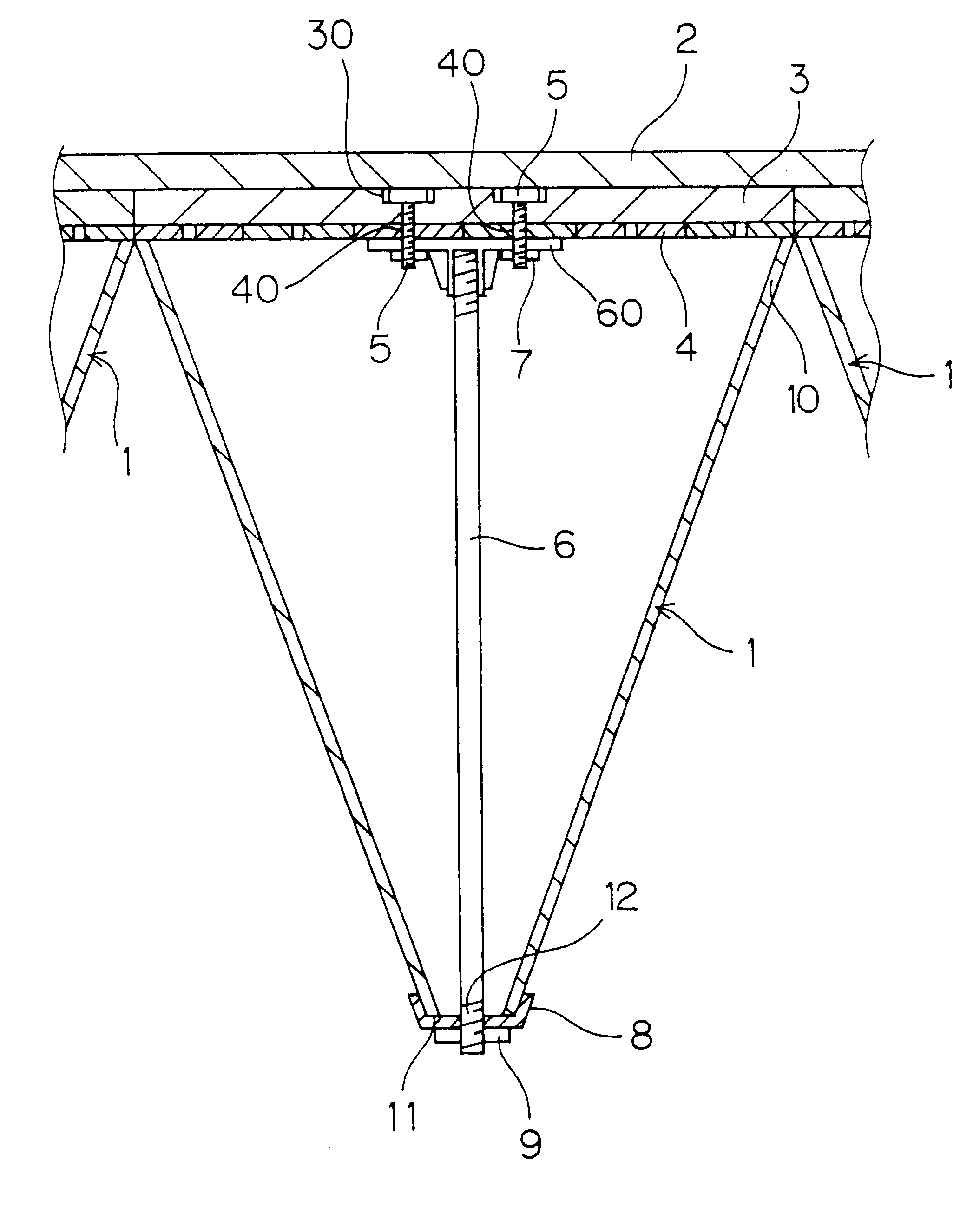
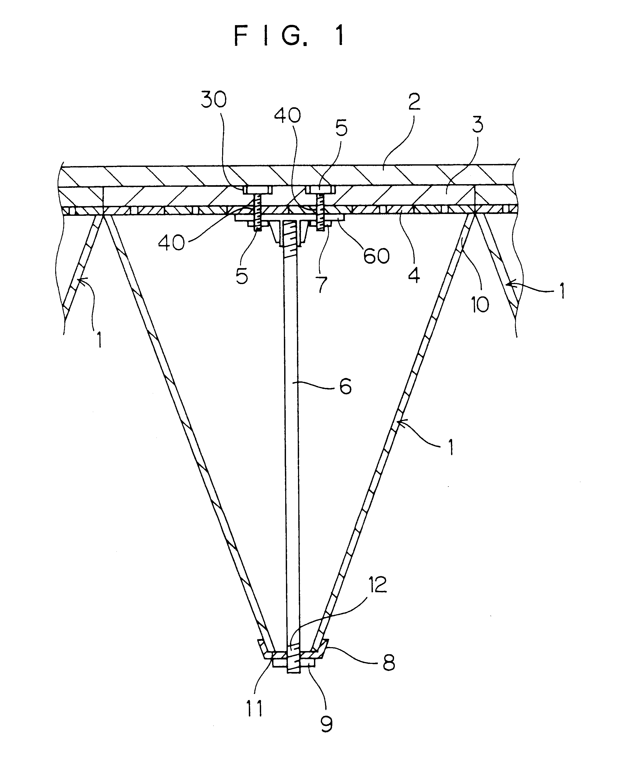
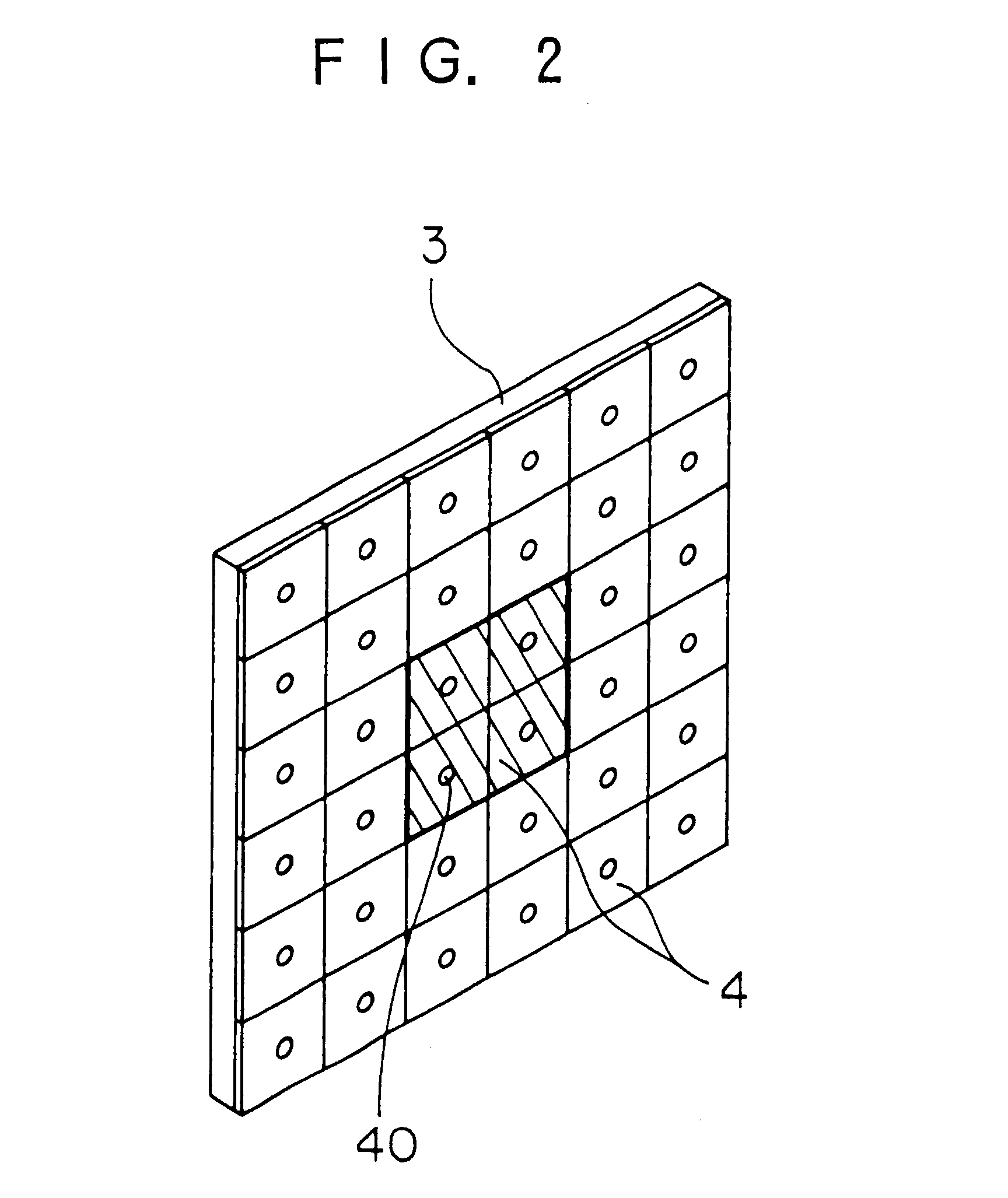
The present invention attains a microwave absorber attachment in a readily, rapidly and stable manner. According to the microwave absorber attaching method and structure of the present invention, a plurality of ferrite plates 4 are bonded to a shield plate 2 at an installation place such as the ceiling, a wall, the floor or the like; the base portion of a support rod 6 is connected to the ferrite plates 4, causing the support rod 6 to project therefrom; a microwave absorber 1 is placed with its base portion placed along the ferrite plates 4; the support rod 6 passes through a tip opening 11 of the microwave absorber 1, causing the support rod 6 to project therethrough; a covering tray 8 allows for the support rod 6 to pass therethrough to cover the microwave absorber 1; and a fastening member is fastened to a tip threaded portion 12 of the support rod 6, thus attaching the microwave absorber 1 to the installation place. The gaps between adjacent ferrite plates 4 are filled with a magnetic sealing agent.
Description
The present invention relates to a method of and a structure for attaching a microwave absorber to the ceiling, a wall, the floor or the like.DESCRIPTION OF RELATED ARTA simulation on electromagnetism jamming or microwave reflection characteristics has conventionally been conducted with the use of a microwave anechoic chamber or a microwave semi-anechoic chamber. For attaching microwave absorbers to the ceiling, walls, floor and the like of such a chamber, there has been employed an adhesive bonding method of bonding the bottoms of the microwave absorbers to the installation sides of the chamber. According to this method, the microwave absorbers are required to be fixed with the use of jigs or frames until the adhesives are perfectly solidified.According to this method, however, such fixation takes time and care should be used such that the microwave absorbers are not damaged in the course of fixation. Thus, this method has never been suitable for attachment of microwave absorbers i...
Claims
Login to View More Application Information
Patent Timeline
 IPC IPC(8): H01Q1/12H01Q17/00H05K9/00
CPCH01Q1/12H01Q17/008H05K9/0003Y10S52/10H05K9/00
Inventor TAKAMATSU, TOSHIYUKITAKAO, TOSHINORISUZUE, MASAYOSHIHARA, HAZIMENAGATA, HIROSHIMORI, KAZUHIKOTANI, MASATOHAMAUZU, TAKASHI
Owner OTSUKA CHEM CO LTD
Features
- R&D
- Intellectual Property
- Life Sciences
- Materials
- Tech Scout
- Unparalleled Data Quality
- Higher Quality Content
- 60% Fewer Hallucinations
Learn More Browse by: Latest US Patents, China's latest patents, Technical Efficacy Thesaurus, Application Domain, Technology Topic, Popular Technical Reports.
© 2025 PatSnap. All rights reserved.Legal|Privacy policy|Modern Slavery Act Transparency Statement|Sitemap|About US| Contact US: help@patsnap.com


