
Membrane with tissue-guiding surface corrugations

a membrane and surface corrugation technology, applied in the field of implants, can solve the problems of limited osteoinductive ability, limited donor site, bone quantity, donor site morbidity, etc., and achieve the effect of only having limited osteoinductive capabilities, limiting donor site, and limited bone allografting procedures

Inactive Publication Date: 2002-05-21
MACROPORE
View PDF7 Cites 137 Cited by
  • Summary
  • Abstract
  • Description
  • Claims
  • Application Information

AI Technical Summary

Problems solved by technology

Allogenic bone graft is known to have osteoconductive and osteoinductive capabilities, although the osteoinductive properties are limited because of the necessary tissue sterilizing and cleaning procedures associated with harvesting these bone grafts.
Bone autografting procedures are typically associated with limitation of donor sites, bone quantity, and donor site morbidity (especially if multiple donor sites are required).
Bone allografting procedures, to begin with, only have limited osteoinductive capabilities.
In addition to the very limited osteoinduction properties of allogenic bone grafts, compared to autograft samples, allografts are immunogenic to a certain degree, bear the risk of disease transmission (e.g. HIV and Hepatitis), and, depending on the size of the allograft, require a long time for ingrowth and partial substitution with new bone.
This long substitution process often requires a time duration of greater than one year before satisfactory clinical results are obtained.
Additionally, pressure from the adjacent musculature may dislocate bone graft material.
Bone grafts may refracture after fixator removal if bone ingrowth and substitution is inadequate.
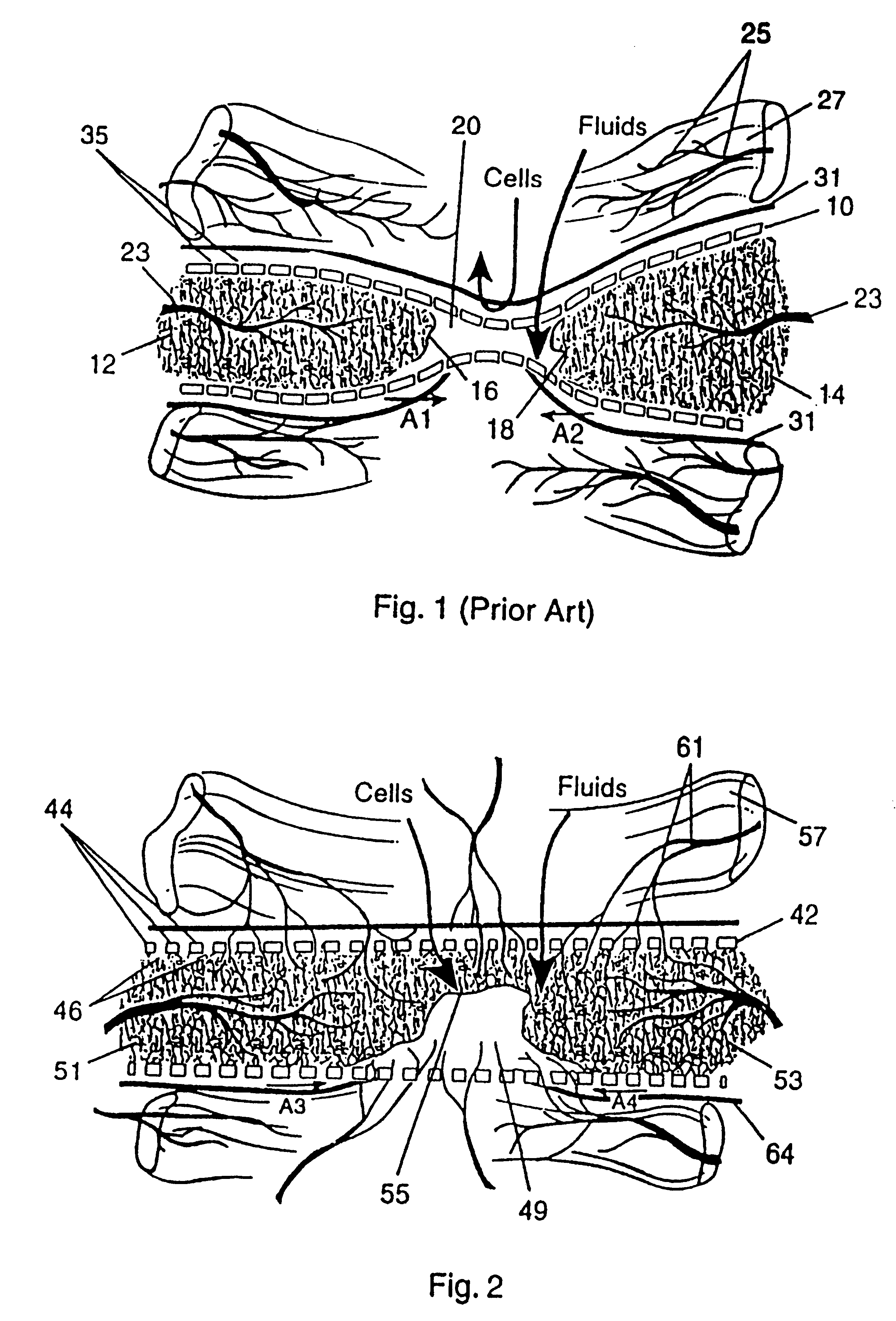
In other areas of the mammalian skeletal system, however, where epithelial cells are not present, these cell-occlusive, fluid-permeable membranes preclude the introduction of blood vessels and surrounding mesenchymal cells for no apparent reason.
Unfortunately, this very thin and flexible configuration, which is somewhat suitable for periodontal and oral applications, is not suitable for maintaining and protecting a sufficiently large bone defect area 20 in non-periodontal and non-oral applications.
Consequently, in order to avoid the risk of bacterial infection, the cell-occlusive, fluid-permeable membrane 10 must be removed during a subsequent operation, which may introduce further complications and risks to the patient.
Thus, in addition to being cell-occlusive, prior membranes suffer from lack of inherent strength and non-resorbability.
To date, any known resorbable material would not be capable of providing the equivalent rigidity and function of the titanium mesh screen.
These screw perforations have diameters (between 4.8 millimeters and 17.5 millimeters), which do not prevent gross prolapse of soft tissues into the bone defect area.
The physical barrier presented by the prolapsing soft tissues greatly impairs new bone formation within the bone defect area.
Any proliferation of blood vessels through these screw holes would be destroyed by any subsequent removal of the fixation device.
The fixation device, if left in the patient, will shield the bone defect area from functional stress and thus prevent an optimal amount of new bone formation.
The prosthetic device is specifically designed as a replacement for the rib cage of a mammalian skeletal system, and does not facilitate bone regeneration.
This is obviously disadvantageous, because its structure reduces the space for new bone regeneration.
The resulting artificial skin graft is obviously not intended for use on the mammalian skeletal system.
This artificial skin graft, in any event, would be far too thin and flexible for use on the mammalian skeletal system, and further would not have adequate fixation strength.

Method used


Image

  • Membrane with tissue-guiding surface corrugations
  • Membrane with tissue-guiding surface corrugations
  • Membrane with tissue-guiding surface corrugations

Examples


Embodiment Construction

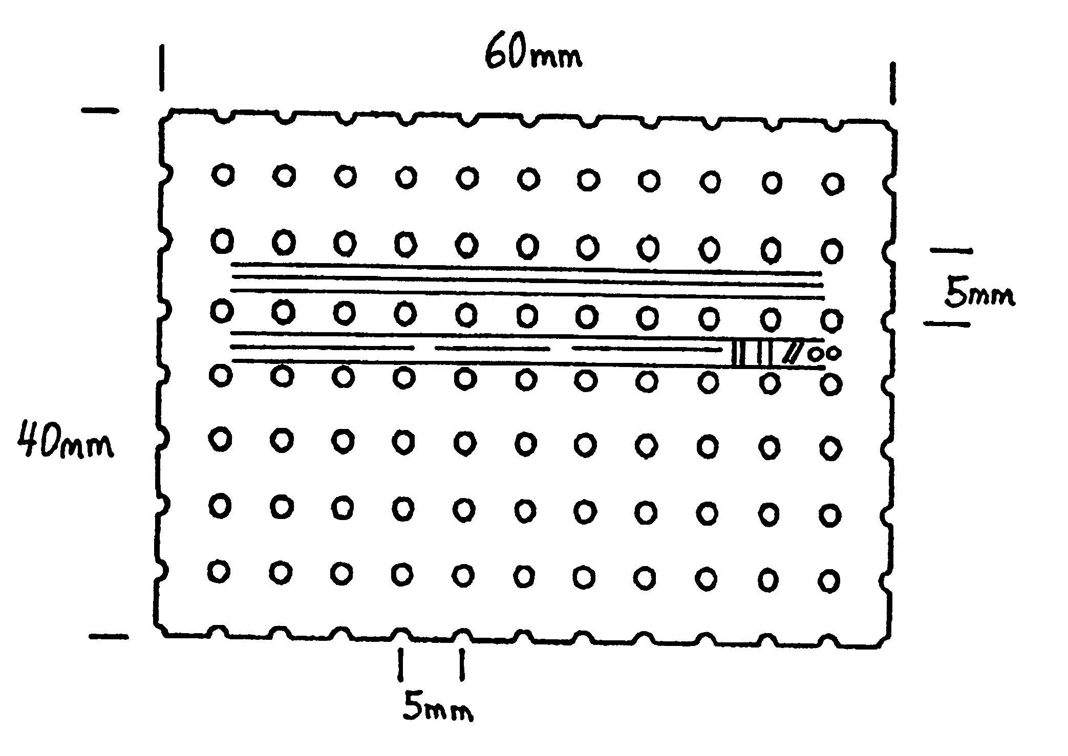
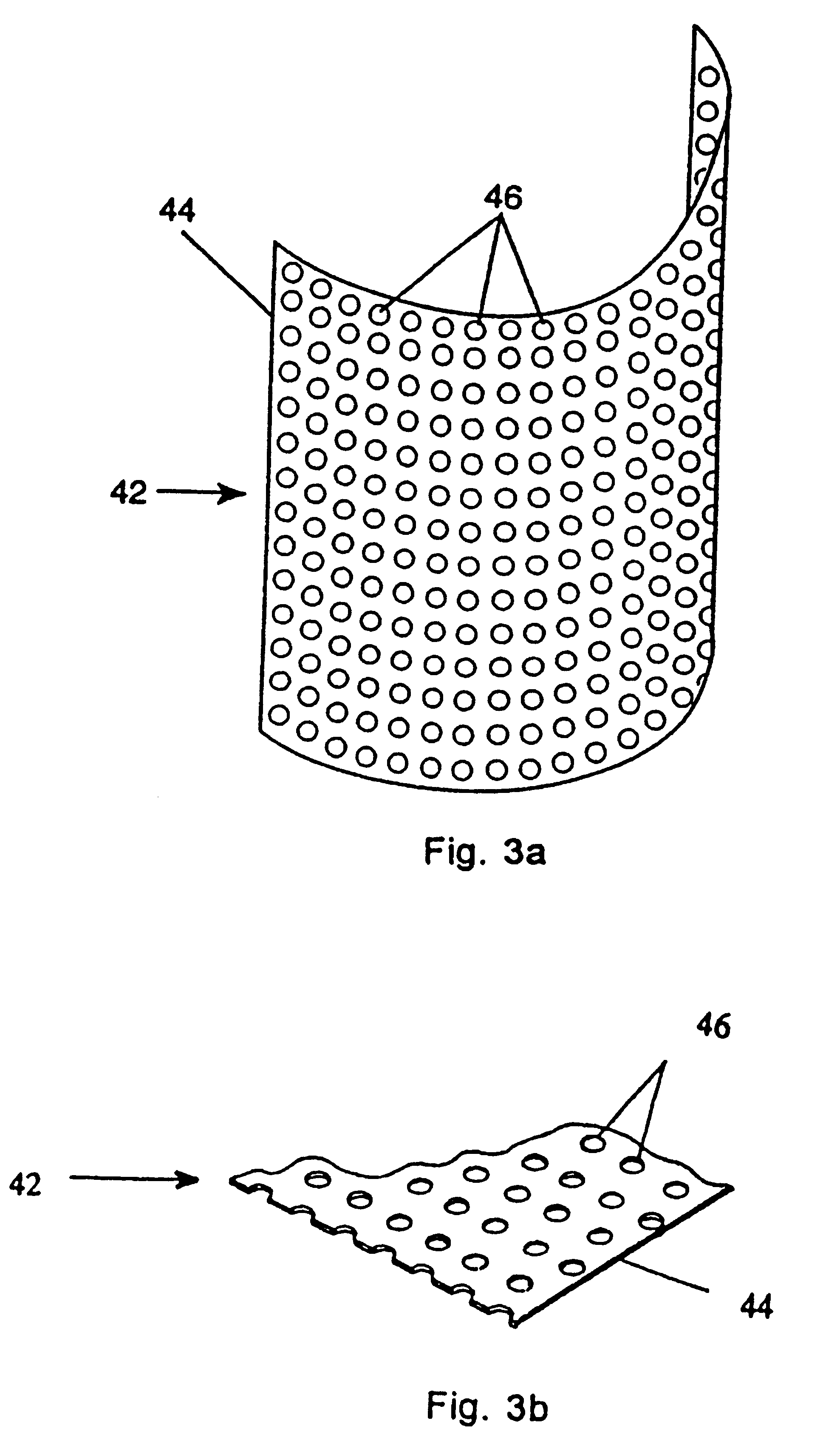
Turning to FIG. 2, a protective bone regeneration membrane 42 is illustrated, comprising a base material 44 and apertures 46. The protective bone regeneration membrane 42 is shown in FIG. 2 wrapped around a bone defect area 49. The bone, which is surrounded by the protective bone regeneration membrane 42, comprises a first section of long bone 51, a second section of long bone 53, and a partially healed intermediate section of long bone 55. The protective bone regeneration membrane 42 is rigid enough to prevent prolapse of the surrounding tissues 57 into the bone defect area 49. Additionally, the apertures 46 of the protective bone regeneration membrane 42 are large enough to allow for a proliferation of blood vessels 61 therethrough and into the first section of long bone 51, the second section of long bone 53, and the partially healed bone defect 49. Since the protective bone regeneration membrane 42 of the presently preferred embodiment is rigid enough to withstand prolapse of th...


PUM

PropertyMeasurementUnit
Timeaaaaaaaaaa
Diameteraaaaaaaaaa
Diameteraaaaaaaaaa

Abstract

A resorbing, flexible implant in the form of a continuous macro-porous sheet (42) is disclosed. The implant is adapted to protect biological tissue defects, especially bone defects in the mammalian skeletal system, from the interposition of adjacent soft tissues during in vitro repair. The membrane (42) has pores with diameters from 20 microns to 3000 microns. This porosity is such that vasculature, and connective tissue cells derived from the adjacent soft tissues including the periosteum, can proliferate through the membrane into the bone defect. The thickness of the sheet is such that the sheet has both sufficient flexibility to allow the sheet to be shaped to conform to the configuration of a skeletal region to be repaired, and sufficient tensile strength to allow the sheet to be so shaped without damage to the sheet. The sheet provides enough inherent mechanical strength to withstand pressure from adjacent musculature, and does not collapse.

Description

1. Field of the InventionThe present invention relates generally to implants for use in repairing various portions of the mammalian skeletal system and, more particularly, to implants for use in clinical procedures such as bone fracture repair, regeneration of bone loss, augmentation of deficient bone, and related procedures.2. Description of Related ArtVarious types of defects in the mammalian skeletal system can be treated by various surgical procedures. Defects in the mammalian skeletal system may include bone fracture, loss of bone occurring from traumatic, surgical, or infectious sources, and bone deficiencies stemming from conditions such as atrophy and congenital anomalies.One procedure that is common in the prior art for treating bone defects involves the placement of additional bone into the bone defect area. This procedure, which is commonly referred to as bone grafting, is the second most frequently performed surgical grafting procedure, with skin grafting the most common...

Claims


Application Information

Patent Timeline
IPC IPC(8): A61B17/68A61B17/80A61F2/28A61L31/14A61L31/00A61L31/16A61L31/18A61C8/00A61F2/00A61F2/02A61F2/30A61F2/46A61B17/03A61B17/00A61B17/064A61B17/08A61B17/06
CPCA61B17/688A61B17/8066A61B17/8085A61F2/2803A61F2/2846A61F2/2875A61L31/005A61L31/148A61L31/16A61L31/18A61B17/06166A61L2300/412A61B17/08A61B17/8061A61B17/8071A61B2017/00004A61B2017/0647A61B2017/0648A61C8/0006A61F2/0077A61F2/28A61F2/30767A61F2002/2817A61F2002/2835A61F2002/2878A61F2002/2889A61F2002/30062A61F2002/30235A61F2002/30428A61F2002/30785A61F2002/30787A61F2002/4649A61F2210/0004A61F2220/0025A61F2230/0069A61L2300/00A61B17/0642
Inventor LEMPERLE, STEFAN M.CALHOUN, CHRISTOPHER J.
Owner MACROPORE
Learn More