
Multi-echo sequence based MR imaging for fluid in motion

a multi-echo sequence and fluid in motion technology, applied in the field of medical magnetic resonance imaging, can solve the problems of prolonged interval between flip and flop pulse, insufficient for stable blood flow detection, and limited versatility

Inactive Publication Date: 2002-04-30
TOSHIBA MEDICAL SYST CORP
View PDF0 Cites 25 Cited by
  • Summary
  • Abstract
  • Description
  • Claims
  • Application Information

AI Technical Summary

Benefits of technology

Another object is to make it possible to image objects whose flow velocities range is wide regardless of magnitudes of flow velocities.

Problems solved by technology

However, the foregoing imaging methods are not enough for stable blood flow detection.
Furthermore, because excessive times for switching gradients are required, the nulling method of gradients is practiced only in cases where flows pass at slower velocities, resulting in a limited versatility.
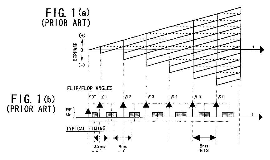
However, in this FSE method cooperatively using the FC and GMN methods, additional gradient pulses are required for the ordinal FSE-basis pulses, resulting in, for example, a prolonged interval between the flip and flop pulses (i.e., the echo train spacing: ETS).
Namely, as the time necessary for practicing the pulse sequence per excitation, data acquisition efficiency is degraded, prolonging the entire imaging time.
Due to this drawback, it will be difficult to steadily catch an object to be depicted, even when the object, such as blood, flows faster.
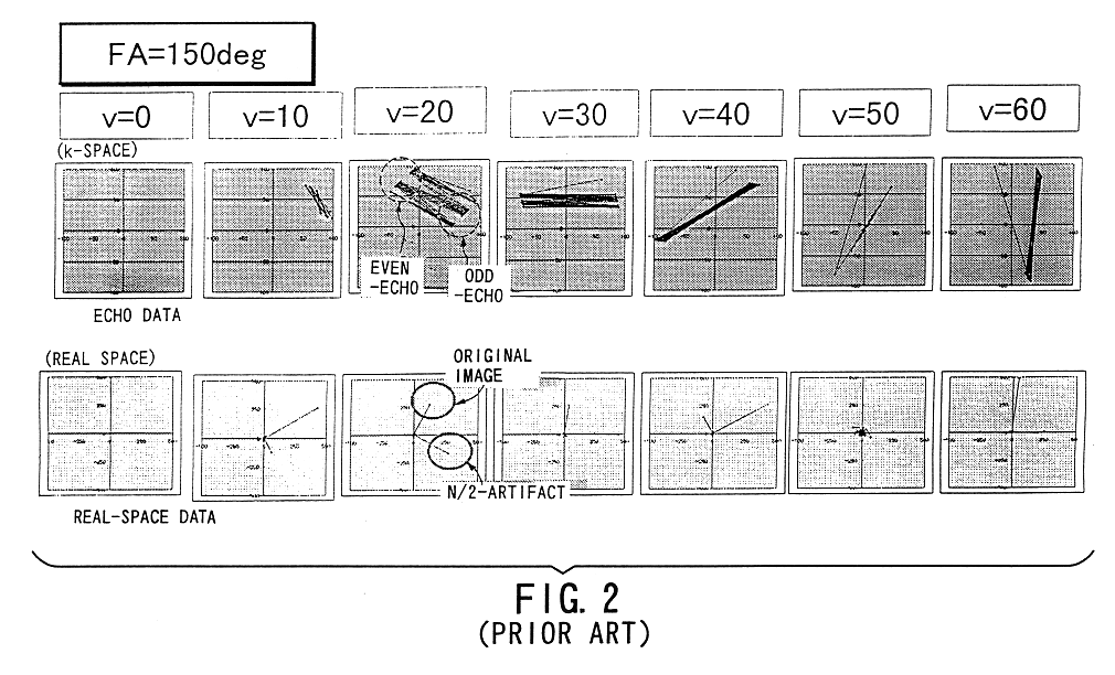
However, the depiction ability along the readout direction is poor and "N / 2 artifacts" occur because of the oscillation of signals on the even and odd echoes.
As shown from those graphs, when the flop angle FA is lowered, the signal oscillation caused between the even and odd echoes become more complicated, resulting in that an image is caused to disappear in states of FA=60 degrees or less.
Under such signal behaviors, one large cause that brings about troubles on images, which has been reported so far, results form the signal oscillation described in the above article 2).

Method used


Image

  • Multi-echo sequence based MR imaging for fluid in motion
  • Multi-echo sequence based MR imaging for fluid in motion
  • Multi-echo sequence based MR imaging for fluid in motion

Examples


first embodiment

An imaging technique according to the present invention will now be described with reference to FIGS. 8 to 10, which is practiced on the VIPS method through the foregoing MRI system. This embodiment is reduced to various modes as follows.

Mode 1:

A mode 1 practices the imaging technique on the VIPS method with a DIET (Dual Interval Echo Train) method. That is, to adjust an amount .o slashed.' of the initial phase shift for an initial echo, the DIET method is used.

The DIET method is known by Japanese Patent Laid-open Publication No. 7-155309 and a paper "H. Kanazawa et al., Contrast Neutralization of Fast Spin Echo Imaging: A Fat Reduction Technique Free from Field Inhomogeneity, 2.sup.nd SMR Scientific Program, p.486, 1994 / 8," of which one mode is that in a pulse sequence on the FSE method, an interval between the application of a 90-degree RF pulse and the acquisition of the first echo is set to odd times of three or more an interval between adjacent two echoes. A practical example i...

second embodiment

Referring to FIG. 11, a second embodiment of the present invention will now be described. This embodiment relates to imaging using a phase contrast method based on the FSE method.

In the FSE-system imaging, satisfying the ".o slashed. / 2" condition causes a phase shift proportional to the product between a gradient moment and a velocity obtained between echoes which sequentially follows the n-th echo. Precisely, as both the gradient moment and velocity take vector quantities of three dimensions, phase shifts to be generated are proportional to their scalar products. Assume that gradient moments are M0' and M0 (M0'=M0 / 2) for a fundamental sequence, where M0 takes three-dimensional vector quantities. This fundamental sequence is shown in FIG. 11(a), and this sequence is referenced by S0.

As a velocity encoding gradient, there is provided a sequence shown in FIG. 11(b), which called A1, where its initial phase MA1' and its repeated phases MA1 are determined so that the relationship of MA1...

third embodiment

A third embodiment of the present invention will be shown in FIG. 12. This embodiment involves blood flow imaging known as lower-flop type of black blood imaging.

Differently from the imaging methods according to the first and second embodiments, the imaging method in this embodiment provides a black blood imaging method that allows signals from blood flows to diminish almost completely.

As shown in FIG. 12, performing data acquisition through a pulse sequence based on an FSE method using a lower flop angle (for example, 90 degrees or less) remarkably decrease a depiction performance for blood flow signals. The third embodiment is derived from this fact, where in multi-echo imaging using refocusing RF pulses (flop pulses), their flop angles are assigned to a lower flop angle (for example, 90 degrees or less) that is unusable for the ordinary FSE imaging. A construction is such that information on this pulse sequence is sent to the sequencer 5 from the host computer 6. This makes it po...


PUM


Abstract

An FSE-system multi-echo MRI pulse sequence is used to steadily depict objects such as blood flows without a contrast medium. The pulse sequence has a gradient pulse set such that, among the plurality of echoes, an amount M' of a j-th (j=1, 1, 2, . . . ) gradient moment accumulated up to an n-th (n=1, 2, 3, . . . ) echo is approximately half an amount M (considered to be approximately constant when k>=n ) of the j-th gradient moment from a k-th (k=n, n+1, n+2, . . . ) echo to a "k+1"-th echo. This pulse sequence is performed and generated multi-echoes are acquired. An MR image is produced using echoes generated after the n-th echo among the acquired multi-echoes. For example, the n-th echo is an echo for n>=2 and a readout gradient to be applied during an interval down to the "n-1"-th echo is altered in time or amplitude, with a given gradient moment.

Description

1. Technical Field of the InventionThe present invention relates to medical magnetic resonance imaging (MRI), particularly, imaging to provide images of objects in motion, such as blood, using multi-echo sequences. Specifically, the present invention relates to imaging that uses an FSE (Fast Spin Echo) method or a FASE (Fast Asymmetric SE) method developed therefrom in order to not only image flows of such objects as blood so as to be depicted more steadily but also to depict a distribution of flow velocities with the help of a technique similar to a phase contrast method.2. Description of Prior ArtMagnetic resonance imaging is based on a technique that magnetically excites nuclear spins of an object placed in a static magnetic field with an RF signal at a Larmor frequency thereof, acquires an MR signal emanated due to the excitation, and reconstructs an image on the basis of the MR signal.In recent years, as one tomographic imaging technique that is frequently used in the field of ...

Claims


Application Information

Patent Timeline
IPC IPC(8): G01R33/54G01R33/563G01R33/561G01R33/48A61B5/055
CPCG01R33/563G01R33/5617
Inventor MACHIDA, YOSHIO
Owner TOSHIBA MEDICAL SYST CORP
Learn More