
Liquid crystal display device

a liquid crystal display and display contrast technology, applied in static indicating devices, instruments, non-linear optics, etc., can solve the problems of unsatisfactory coloration, difficult to improve the display contrast of the liquid crystal display device, and unable to achieve uniform density distribution of ball-like spacers

Inactive Publication Date: 2002-04-23
JAPAN DISPLAY CENTRAL CO LTD
View PDF8 Cites 47 Cited by
  • Summary
  • Abstract
  • Description
  • Claims
  • Application Information

AI Technical Summary

Benefits of technology

One object of the present invention is to provide a high-dignity liquid crystal display device substantially unaffected by environmental temperature change in which spacers are disposed on a substrate.
With that structure, the cell gaps can be adjusted in response to thermal constriction of the liquid crystal material at lower temperatures so that the generation of bubbles is prevented.
With this particular structure, the spacers sufficiently change in length even at the environmental temperature of -20.degree. C. to adjust the cell gaps in response to the thermal constriction of the liquid crystal so that the generation of bubbles are effectively prevented. Further, since the length change Y of the spacers at the environmental temperature of 20.degree. C. is controlled to be less than 2X .mu.m, the function of the spacers to maintain uniform cell gaps is not substantially affected. Thus, the generation of bubbles is further prevented while the uniform cell gaps are maintained in a wide temperature range.

Problems solved by technology

It is quite important to keep a gap between the electrode substrates substantially constant because, otherwise, undesired coloration occurs when the liquid crystal display device is in operation.
The ball-like spacers, however, can hardly achieve their uniform density distribution and the constant cell gap between the substrates.
Further, some ball-like spacers pass light even on a light blocking mode of the liquid crystal display device.
Thus, it is difficult to improve display contrast of the liquid crystal display device.
Lower temperatures are particularly apt to cause bubbles.

Method used


Image

  • Liquid crystal display device
  • Liquid crystal display device
  • Liquid crystal display device

Examples


Embodiment Construction

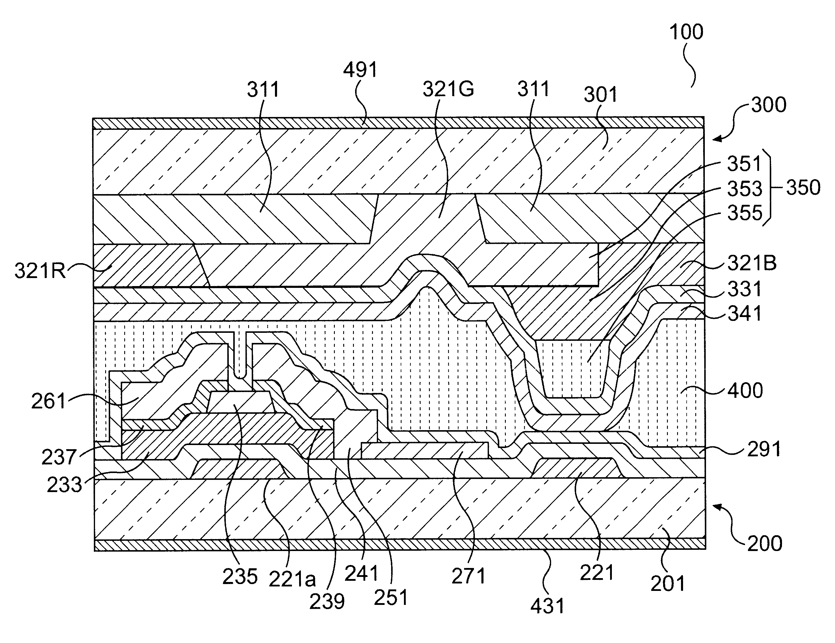
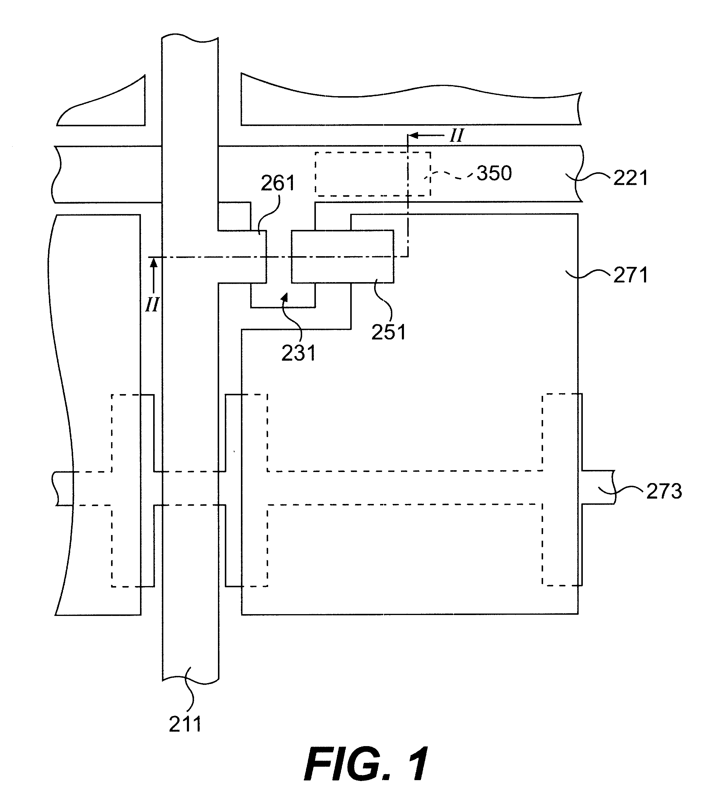
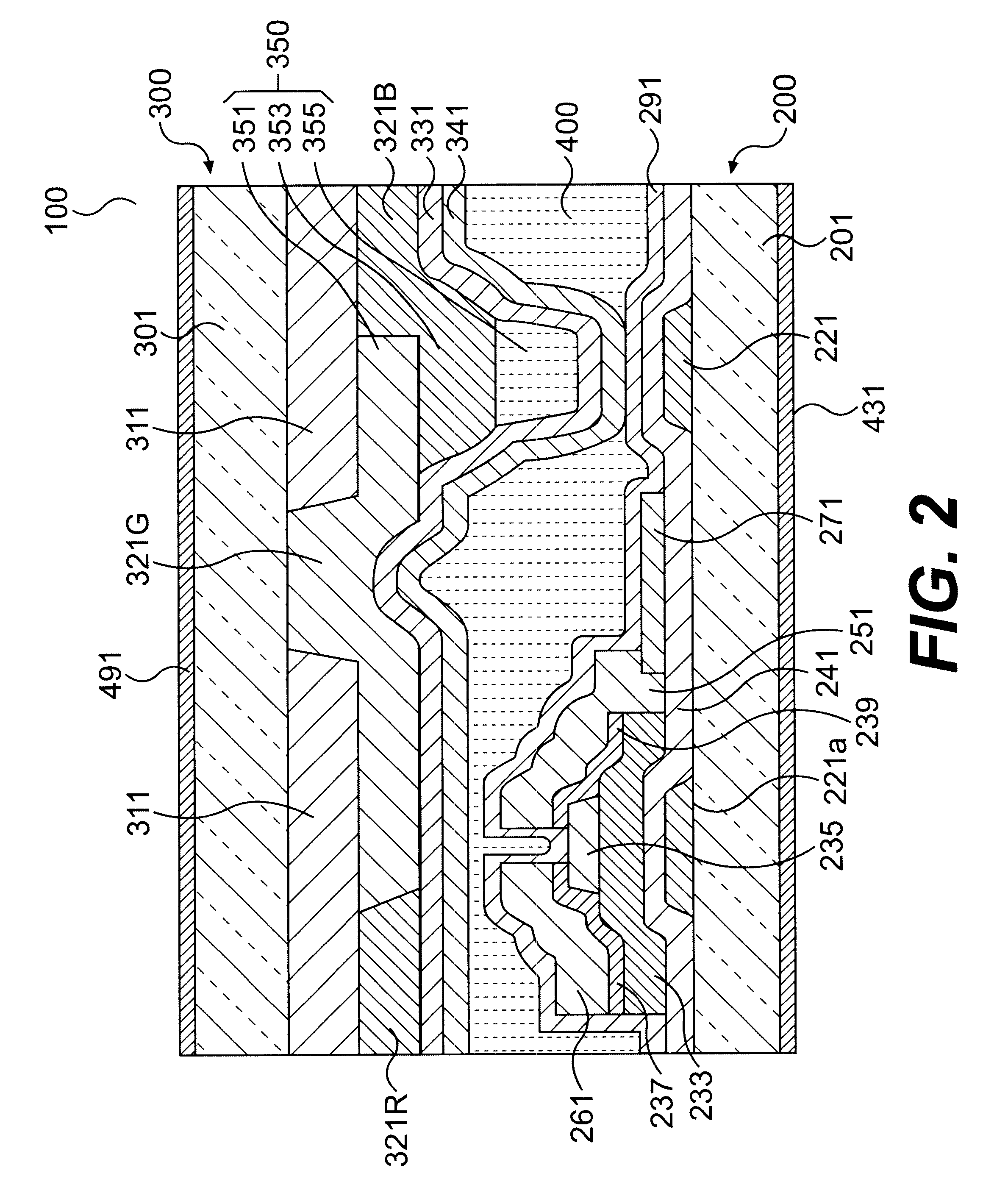
First, principles of the present invention will be briefly explained hereinafter. In order to prevent the generation of bubbles, spacers of the invention are used to follow change in volume of a liquid crystal material due to environmental temperature variations. The inventors' experiment has revealed that the cell gap constriction is caused by change in volume of a liquid crystal material in response to the environmental temperature variations. Depending on materials and structure of a cell gap, and cell gap shrinks by about 0.09 .mu.m, for instance, due to the environmental temperature change from 20.degree. C. to 0.degree. C. on the condition that the liquid crystal material No. TC-5140 manufactured by Chisso Corporation is put into the cell gap of 5 .mu.m of the liquid crystal display device which has an effective rectangular display region with 12.1 -inch diagonal length. The cell gap reduced by more than 0.1 .mu.m, e.g., by about 0.15 .mu.m, in response to the environmental te...


PUM

PropertyMeasurementUnit
pressureaaaaaaaaaa
temperatureaaaaaaaaaa

Abstract

A liquid crystal material is held between a circuit array and counter substrates. A plurality of spacers are disposed to keep a gap between the circuit array and counter substrates substantially constant. Change in distance of the gap equivalent to constriction of the liquid crystal material due to change in temperature from 20.degree. C. to -20.degree. C. is less than change in height of the spacers on conditions that the pressure of 100 mN / nm2 is applied between the substrates and that the liquid crystal material is not held between the substrates.

Description

BACKGROUND OF THE INVENTION1. Field of the InventionThis invention relates to a liquid crystal display device and, more particularly, to a liquid crystal display device with spacers to keep a gap between its substrates substantially constant.2. Description of the Prior ArtA liquid crystal display device is light in weight, thin in thickness and low in power consumption so that it has been widely used in various applications. In such a liquid crystal display device, a twisted nematic (TN) type liquid crystal material is held between a pair of electrode substrates.It is quite important to keep a gap between the electrode substrates substantially constant because, otherwise, undesired coloration occurs when the liquid crystal display device is in operation. In order to comply with such a requirement, ball-like spacers are scattered on one of the substrates in a predetermined density distribution. The substrate is then put together with another substrate. The gap is often referred to as...

Claims


Application Information

Patent Timeline
Patent Type & Authority Patents(United States)
IPC IPC(8): G02F1/13G02F1/1339
CPCG02F1/13394G02F1/1339
Inventor MORIMOTO, HIROKAZUNISHINO, TETSUYA
Owner JAPAN DISPLAY CENTRAL CO LTD
Learn More