
Method of provisioning nodes within a communications network

a technology of provisioning nodes and communications networks, applied in the direction of data switching networks, data switching by path configuration, digital transmission, etc., can solve problems such as non-synchronized gtt nodes, network congestion or possibly even network failure of ss7, and achieve the effect of reducing the problem

Inactive Publication Date: 2002-04-09
RPX CLEARINGHOUSE
View PDF5 Cites 28 Cited by
  • Summary
  • Abstract
  • Description
  • Claims
  • Application Information

AI Technical Summary

Benefits of technology

Sequential provisioning of networks in accordance with the invention advantageously mitigates the problem of signalling messages looping while networks are in a non synchronized state. The method proposed works equally well where one or more intermediate networks are involved. Significant savings can be realized to service providers as little or no development is required at the network element level.

Problems solved by technology

The United States is likely ahead of most other LNP interested countries in its deployment of LNP and as a consequence is experiencing first hand many of the problems associated with such a network impacting service.
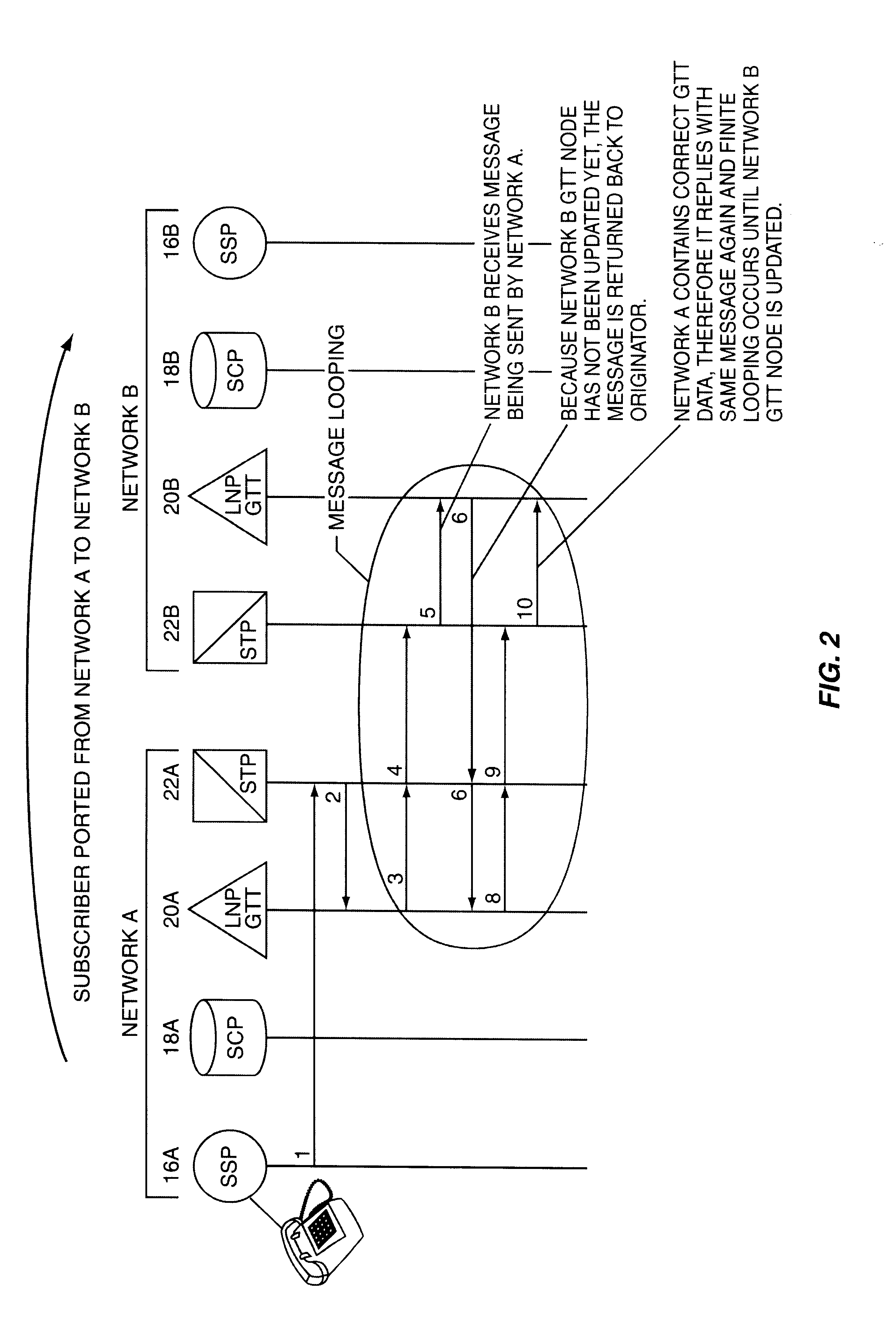
If a call is encountered during this interval when network GTT nodes are not synchronized, SS7 message looping is likely to occur and will cause SS7 network congestion or possibly even network failure.
The problem of non synchronized GTT nodes exists simply because GTT nodes across the network can not all be provisioned simultaneously.
However as is outlined in the ICC Final draft the participants have stated that such a method had two major flaws; first that it "will not protect against looping, when a transport (intermediate) network is used that performs GTT, without following an operational protocol"; and secondly that "this operational protocol does not currently exist".

Method used


Image

  • Method of provisioning nodes within a communications network
  • Method of provisioning nodes within a communications network
  • Method of provisioning nodes within a communications network

Examples


Embodiment Construction

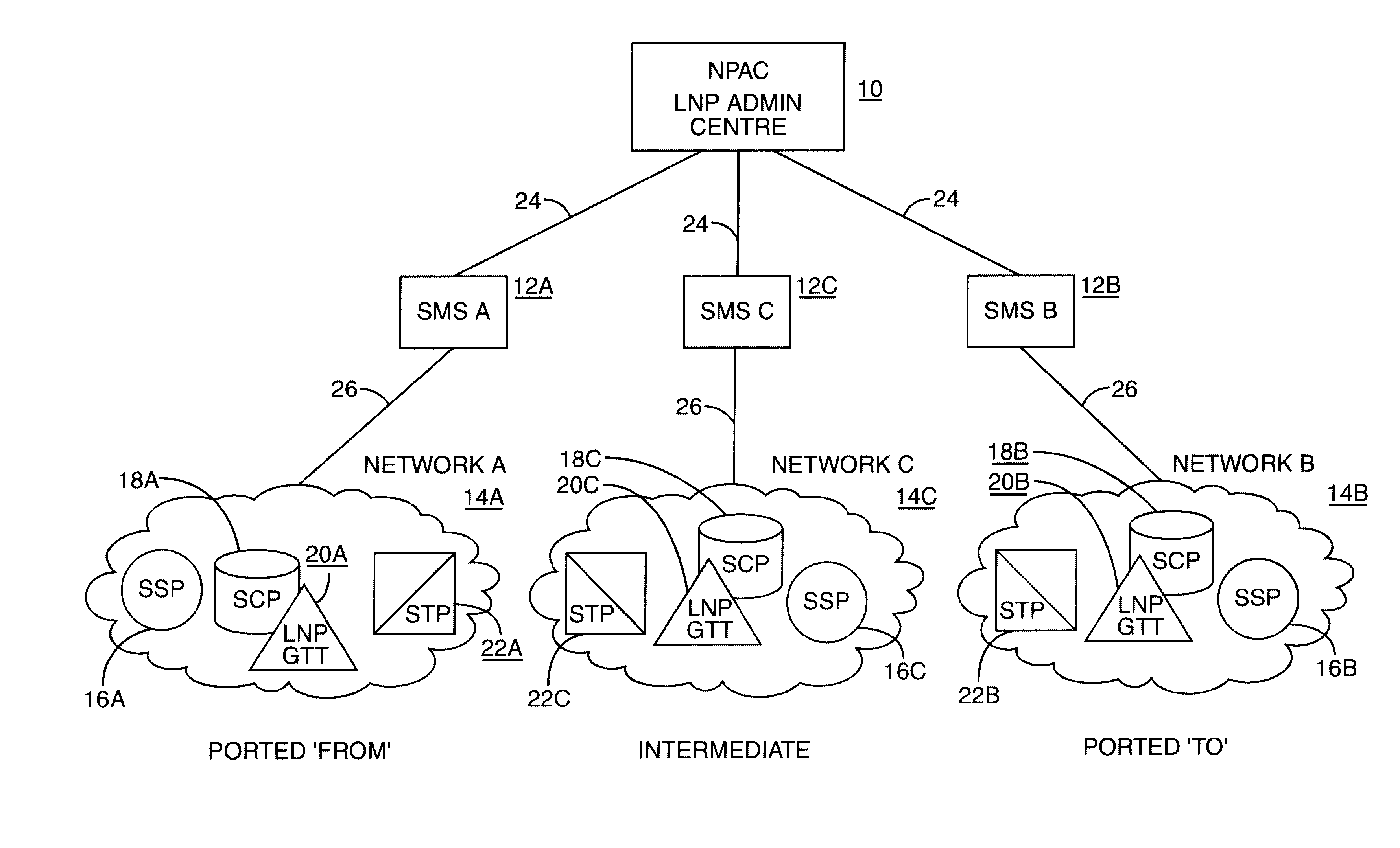
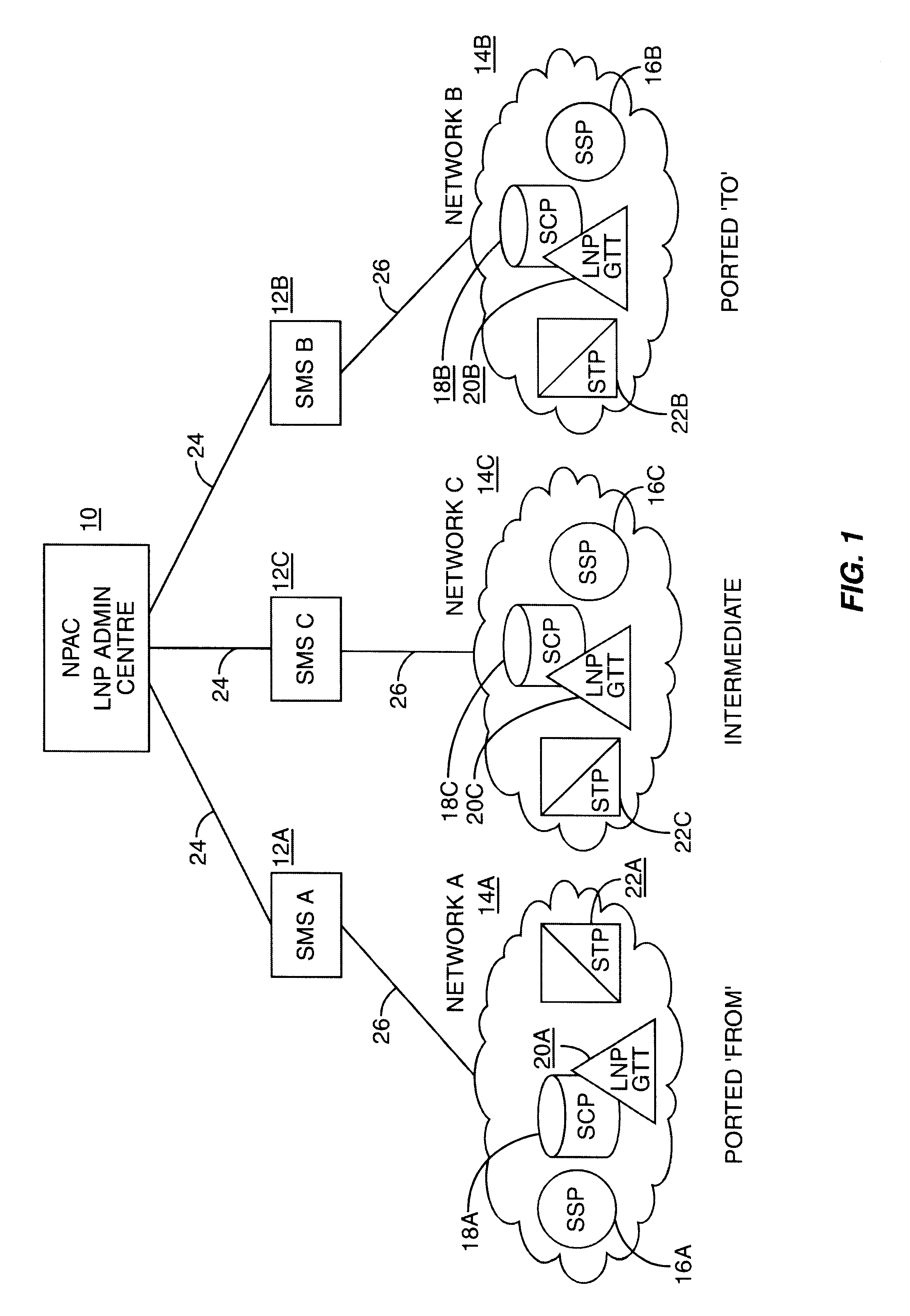
FIG. 1 illustrates a preliminary proposal by the ICC Workshop on Local Number Portability of an architecture for administrating and monitoring a larger LNP capable network which is comprised of numerous LNP capable Service Provider networks. Three separate service provider networks, Network A, B and C are represented within clouds 14A, 14B, 14C respectively in FIG. 1. Each network comprises well known network functionality such as Service Switching points (SSP) 16A, B, C, Signal Transfer Points (STP) 22A, B, C and Service Control Points (18A, B, C). Included in each of the three Networks 14A, B, C is a LNP GTT function 20A, B, C which although shown separately may be provided by an SCP that also provides the LNP application or the function may reside elsewhere in the network. Each network 14A, B, C is connected over proprietary links 26 to respective local Service Management System (SMS) 12A, B, C which are the operations and support system for Advanced Intelligent Networks (AIN) an...


PUM


Abstract

A method of provisioning a local number portability capable communication network which comprises numerous service provider networks, with updated signalling routing information to reflect a porting change is disclosed. A central administration center first updates the ported to network with updated signalling routing information. After the ported to network has been successfully updated the central administration center then proceeds to update all intermediate service provider networks. After confirmation has been received that all intermediate networks have been successfully updated the central administration center then proceeds to update the ported from network. Provisioning of networks which include intermediate networks supported by a central administration center in the predetermined manner and sequence disclosed can advantageously prevent signalling messages from looping between non-synchronized networks. The provisioning sequence works equally well where only two networks are involved, i.e. the ported from and ported to networks.

Description

FIELD OF INVENTIONThis invention relates to provisioning nodes within a telecommunications network and in particular to updating nodes with new signalling routing data for local number portability applications.BACKGROUND TO THE INVENTIONLocal Number Portability (LNP) is a new capability or service that allows end-users of telecommunications services to retain their existing telephone directory number (DN) when for example they either change from one geographic location to another or change from one service provider to another.Local Number Portability (LNP) will likely be a service which will be ubiquitous throughout telecommunications networks. The United States is likely ahead of most other LNP interested countries in its deployment of LNP and as a consequence is experiencing first hand many of the problems associated with such a network impacting service.It is generally realized that service providers (SP) and other interested groups will have to co-operate in defining how LNP wil...

Claims


Application Information

Patent Timeline
IPC IPC(8): H04Q3/00
CPCH04Q3/005H04Q3/0025
Inventor BOJANIC, ALEXANDER
Owner RPX CLEARINGHOUSE
Learn More