
Heat recovery and pollution abatement device

a technology of heat recovery and pollution abatement, which is applied in the direction of sulfur compounds, alkali metal sulfides/polysulfides, separation processes, etc., can solve the problems of loss of thermodynamic efficiency, high gas velocity through steel economizers, and more costly alloys

Inactive Publication Date: 2002-02-05
ALTIRA TECH FUND V
View PDF15 Cites 39 Cited by
  • Summary
  • Abstract
  • Description
  • Claims
  • Application Information

AI Technical Summary

Problems solved by technology

kJ). Gas velocities through steel economizers are not high and transfer rates ar
For economic reasons, it is customary to use low-carbon steel in the inlet sections of the super heater, and, progressively, more costly alloys as the metal temperatures increase.
Excessive liquid or vapour flow rates, while providing lower tube-metal temperatures, should be avoided, since they result in high pressure drop with consequent loss of thermodynamic efficiency.
However, small quantities of carbon monoxide and partially reacted flue constituents in the form of gases and liquid or solid aerosols may also form.

Method used


Image

  • Heat recovery and pollution abatement device
  • Heat recovery and pollution abatement device
  • Heat recovery and pollution abatement device

Examples


example 2

For the analysis in Example 1 find, per cubic foot (per m.sup.3) of fuel gas, the cubic feet (m.sup.3) of dry air required for combustion, the cubic feet (m.sup.3) of each constituent in the flue gases, and the total volume of dry and wet flue gases.

The volume of dry air required for combustion is:

(9.57)(CH.sub.4)+(16.75)(C.sub.2 H.sub.6)=9.57.times.0.90+16.75.times.0.05=9.45 cu.ft / cu.ft(m.sup.3 / m.sup.3)gas

The constituents per cubic foot (per m.sup.3) of flue gas are:

Total Water Vapour

Total volume of dry gas per cubic foot (per m.sup.3) of gas:

8.64+0.31+1.00=9.95 cu.ft. (0.28 m.sup.3)

Total volume of wet gases per cubic foot (per m.sup.3) of gas (neglecting water vapour in combustion air)

9.95+1.95=11.90 cu.ft. (0.357 m.sup.3)

The cubic feet of dry flue gas per cubic foot (per m.sup.3) of fuel gas that may also be computed from equation is as follows:

(1.00)(100) / 10.0=10 cu. ft (0.28 m.sup.3)

Combustion of Gaseous and Liquid Fuels

Combustion equation is the approximate molecular weights ...


PUM

PropertyMeasurementUnit
Lengthaaaaaaaaaa

Abstract

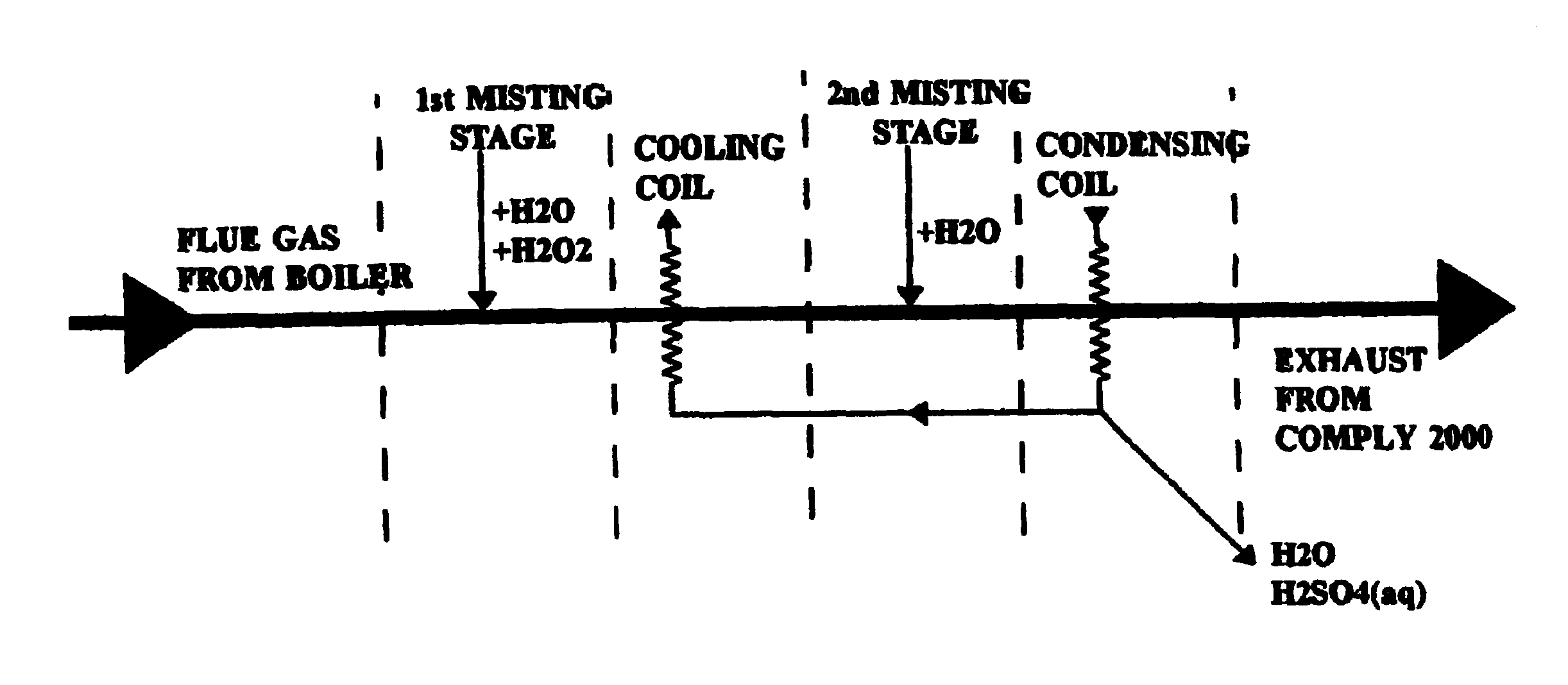
A heat recovery and pollution abatement process with stackless operation for removing the products of combustion from hot boiler flue gas (45) comprising the steps of passing said hot boiler flue gas through a cloud of steam or mist (46), cooling the hot moist flue gas and recovering the heat therefrom (47), passing the partly cooled hot moist flue gas through a second cloud of mist comprised of cold water to total saturation (48), collecting the resulting stream of acid water, forcing the treated flue gas, mixing the treated flue gas with outside air, directing the forced treated air to atmosphere, shutting off the process in the absence of boiler flue gas.

Description

DESCRIPTIONThis invention relates to a pollution abatement process and pollution abatement device which makes use of misting technology, together with cooling and condensation coils to effect targeted pollutants' removal. It accomplishes these objectives with little wastewater generation and the use of reactants for specific pollutants. The invention eliminates the need for an exhaust stack, creating a huge savings for any facility from reduced stack maintenance costs, elimination of stack replacement costs and the elimination of boiler operations for stack warming.GeneralAccording to the Principle of Environmental Control (cited by Marks' Standard Handbook of Mechanical Engineers, Ninth edition), nature has provided two almost inexhaustible sumps for maintaining a steady-state environment on earth. The first of these is the 3 K background temperature of absolute space, which nature uses for heat rejection to close its heat balances. The second is the oceans, which serve to close th...

Claims


Application Information

Patent Timeline
IPC IPC(8): B01D47/00B01D47/05B01D53/00B01D53/40
CPCB01D47/05B01D53/40B01D53/002Y02P70/10
Inventor LITTLEFORD, WAYNE SCOTT
Owner ALTIRA TECH FUND V
Learn More