
High speed demodulation systems for fiber optic grating sensors

a technology of fiber optic grating and demodulation system, which is applied in the direction of optical radiation measurement, photometry using electric radiation detector, instruments, etc., can solve the problems of limited multiparameter distributed sensing, limited the utility of this approach, and the inability to achieve reasonable accuracy using conventional single mode fiber widely separated wavelengths, etc., to achieve high-speed multiparameter sensing and improve the accuracy and speed of measuremen

Inactive Publication Date: 2002-01-01
NAGANO KEIKI
View PDF9 Cites 54 Cited by
  • Summary
  • Abstract
  • Description
  • Claims
  • Application Information

AI Technical Summary

Benefits of technology

In the present invention high speed demodulation systems are described for supporting one or more fiber grating sensors that are subject to temperature, longitudinal strain, transverse strain or other environmental parameters that result in a change in their spectral response. This invention improves the accuracy and speed of measurements made on fiber grating sensors formed on birefringent optical fiber by identifying the minimal number of spectral peak positions that must be measured to insure an accurate result. For the case of dual wavelength fiber gratings written onto birefringent fiber this involves selecting two or three of the four possible spectral peaks to process to allow rapid measurement of axial strain and temperature, or pressure, or three axes of strain. Very high speed demodulation and multiplexed fiber grating sensor systems can be supported by employing ratiometric techniques that use chirped fiber gratings, overcoupled couplers or Mach-Zehnder or Michelson interferometers in combination with appropriately placed fiber grating filters. By combining these techniques it is possible to support very high speed multiparameter sensing using fiber gratings.
Another object of the invention is to provide higher speed performance while retaining the accuracy of measurements.
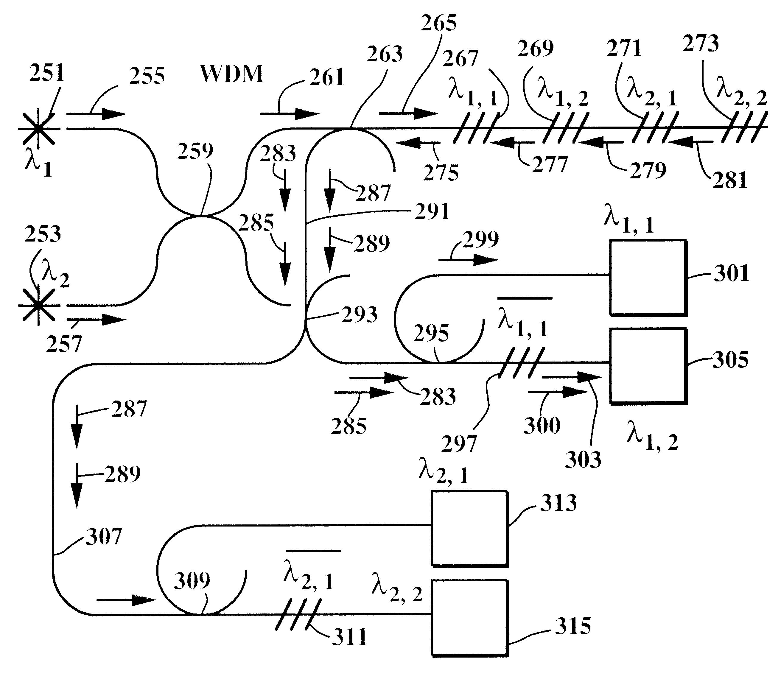
FIG. 8 is a diagram of a demodulation system supporting multiplexed fiber grating sensors in a single line that uses fiber grating blocking filters in front of ratiometric demodulation systems to improve performance. The ratiometric demodulators could be based on chirped fiber gratings, Mach-Zehnder or overcoupled coupler configurations.
FIG. 18 shows a block diagram of a multiparameter fiber grating sensor system configured to support series of multiparameter fiber grating sensors in a single line with processing options to increase overall speed.
FIG. 20b illustrates how transverse strain modulating peak to peak spectral separation results in a net amplitude change in light propagating past the variable filter spectral profile. Variable modulation of the position of spectral peak profile can be used to accurately position the filter between the dual peaks.

Problems solved by technology

The major difficulty with this approach is that to obtain reasonable accuracy using conventional single mode fiber widely separated wavelengths must be used.
These two wavelengths are far enough apart to have modest strain and temperature resolution but problems associated with bend loss and high attenuation in conventional fibers have severely limited the utility of this approach.
The current models run at 5 to 7 kHz and are designed to monitor one single element fiber grating sensor severely limiting their ability to support multiparameter distributed sensing.

Method used


Image

  • High speed demodulation systems for fiber optic grating sensors
  • High speed demodulation systems for fiber optic grating sensors
  • High speed demodulation systems for fiber optic grating sensors

Examples


Embodiment Construction

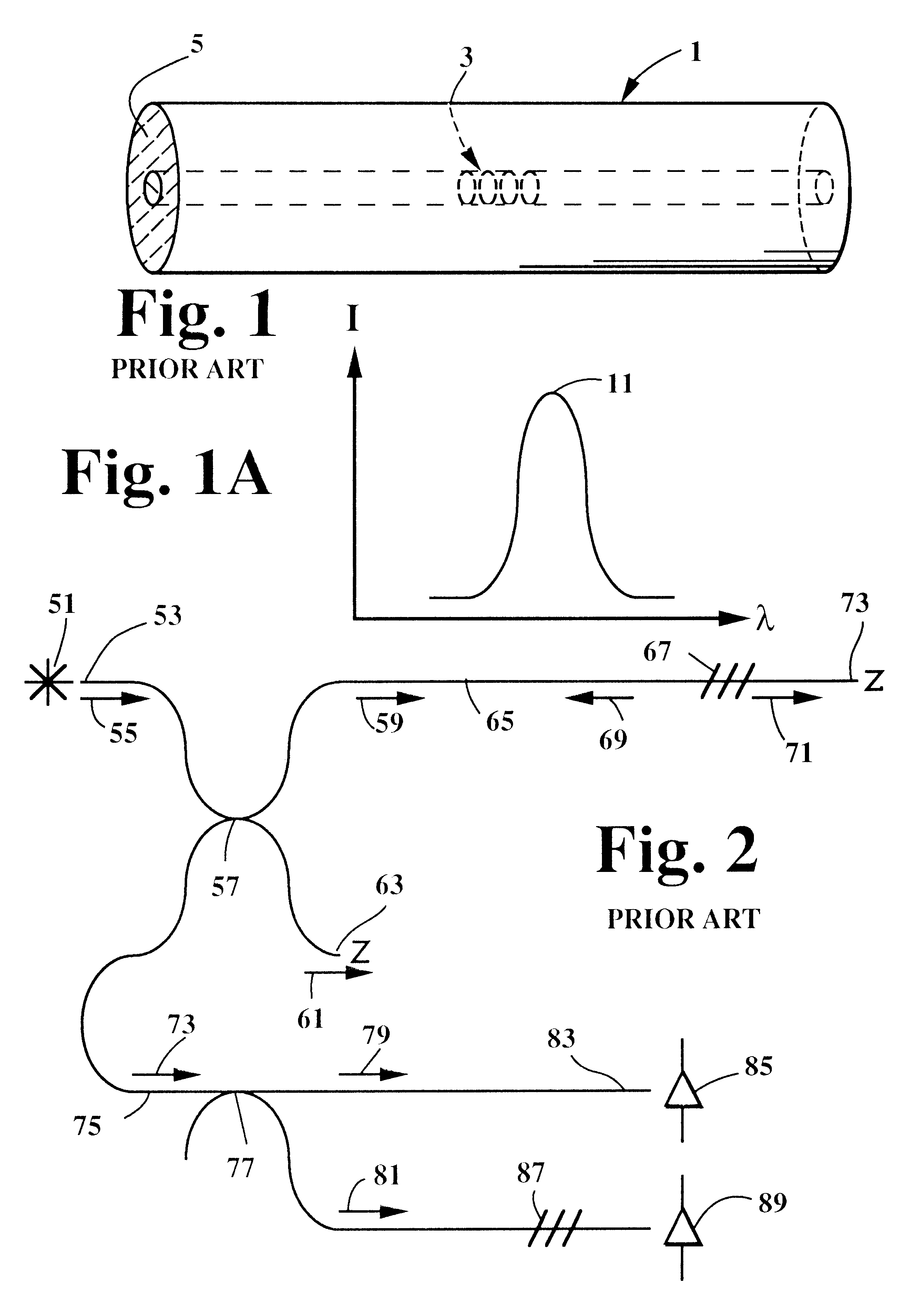
FIG. 1 shows a prior art fiber grating sensor based on writing a single grating onto optical fiber. The fiber grating sensor 1 consists of fiber grating 3 written onto a length of optical fiber 5. FIG. 1 a shows the spectral reflective output 11 from the sensor in FIG. 1.

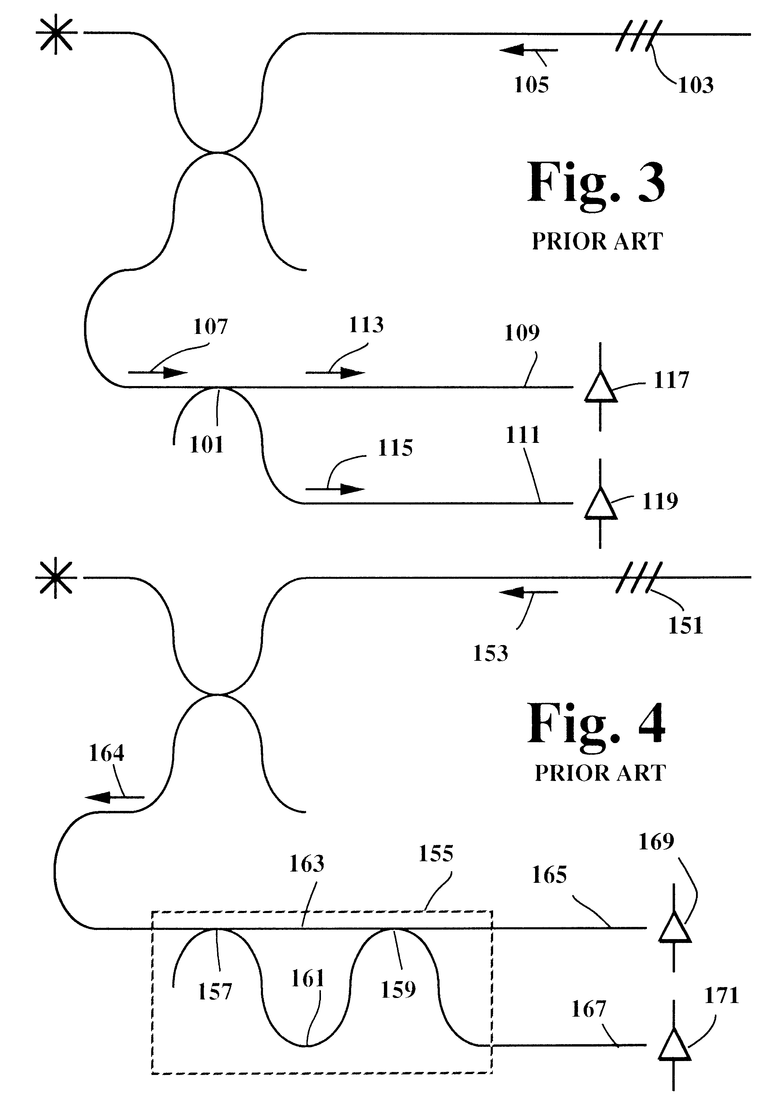
FIG. 2 illustrates a prior art high speed fiber grating demodulation system based on using a ratiometric configuration with a fiber grating filter. The usage of a fiber grating to measure fiber grating sensor wavelength shifts if described by E. Udd and T. Clark in U.S. Pat. No. 5,380,995. In the case of the configuration of FIG. 2, light from a source 51 is coupled into a fiber end 53 and directed as light beam 55 to the central fiber beamsplitter 57. The light beam 55 is split into the light beams 59 and 61. The light beam 61 is directed toward the terminated end 63 which is designed to minimize back reflection and exits the system. The light beam 59 propagates down the fiber 65 and a portion of it 69 reflects off...


PUM


Abstract

Fiber optic grating sensor demodulation systems are described that offer high speed and multiplexing options for both single and multiple parameter fiber optic grating sensors. To attain very high speeds for single parameter fiber grating sensors ratio techniques are used that allow a series of sensors to be placed in a single fiber while retaining high speed capability. These methods can be extended to multiparameter fiber grating sensors. Optimization of speeds can be obtained by minimizing the number of spectral peaks that must be processed and it is shown that two or three spectral peak measurements may in specific multiparameter applications offer comparable or better performance than processing four spectral peaks. Combining the ratio methods with minimization of peak measurements allows very high speed measurement of such important environmental effects as transverse strain and pressure.

Description

For many structural applications fiber gratings have been proposed as a method to measure strain. A great deal of work has been done investigating the usage of fiber gratings to measure axial strain and temperature. In many cases that involve embedment into a structure, the fiber grating is subject to transverse strain that may result in a spectral shift on the order of the spectral shifts resulting from longitudinal strain and or temperature shifts. E. Udd in U.S. Pat. No. 5,591,965, Jan. 7, 1997 describes a three axis strain and temperature fiber grating sensor formed by writing two overlaid fiber gratings onto birefringent fiber. As an example wavelengths of the fiber gratings can be written at 1.300 and 1.550 microns. By writing onto the highly birefringent fiber four gratings are established. In the case of about a two millimeter beat length at 630 nm they would be at 1300.0, 1300.6, 1550.0 and 1550.8 nm. The birefringent axes are well defined so that transverse strain can be m...

Claims


Application Information

Patent Timeline
Patent Type & Authority Patents(United States)
IPC IPC(8): G01D5/353G01D5/26
CPCG01D5/35383
Inventor UDD, ERICWEISSHAAR, ANDREAS
Owner NAGANO KEIKI
Learn More