
Fluid tank drain pipe support/guide member

a technology for drain pipes and fluid tanks, applied in tank vehicles, transportation and packaging, transportation items, etc., can solve problems such as difficult to detect the presence of fluid between the liner and the side wall of the tank, and the leakage of fluid,

Inactive Publication Date: 2001-12-11
GATX RAIL CORP +1
View PDF4 Cites 15 Cited by
  • Summary
  • Abstract
  • Description
  • Claims
  • Application Information

AI Technical Summary

Benefits of technology

In accordance with the present invention an improved drain pipe support / guide structure prevents the insertion of a drain pipe into a fluid tank from damaging the interior liner. The novel structures of the present invention also allow fluid to freely flow from the fluid filled tank through the drain pipe support / guide and advantageously guides the drain pipe while it is being inserted into the fluid tank to prevent contact between the drain pipe and the interior protective liner of the tank.
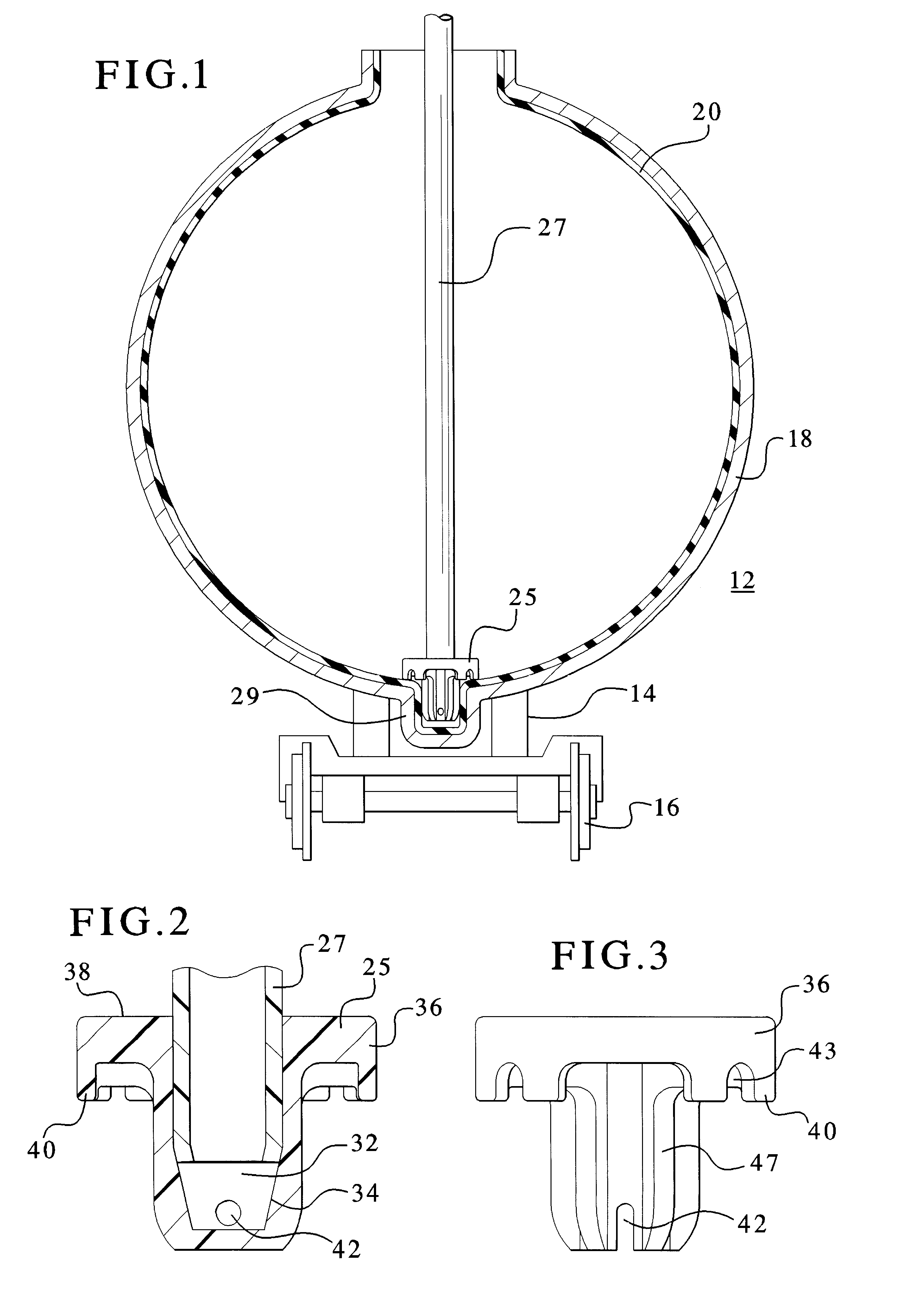
In accordance with the present invention, a hollow metal fluid filled tank includes a protective inert inner liner that covers the entire inner surface of the tank thereby preventing any contact between the side walls of the tank and any corrosive fluids or acids contained within the tank. The protective liner is employed in order to prevent corrosive fluids such as acids from corroding a leak path through the interior surface of the tank which is typically comprised of metal. The present application discloses a fluid tank drain pipe support / guide which acts as a guide and / or support for the drain pipe while also eliminating the potential for tearing the tank liner. In an exemplary embodiment, the drain pipe support / guide has a sufficiently large footprint to prevent the insertion of the drain pipe at an angle other than perpendicular to the floor of the tank from resulting in contact between the drain pipe and the protective inert liner located on the sidewall of the tank car.
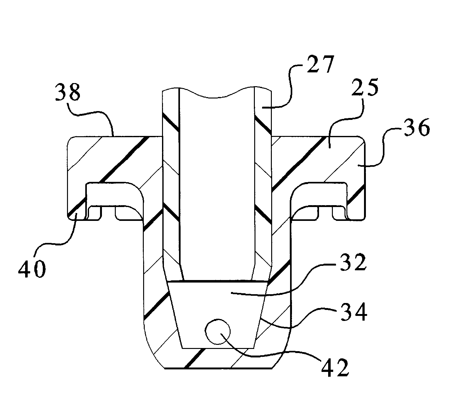
The drain pipe support / guide advantageously serves several features. It acts as a guide for insertion of the drain pipe. In this regard, when the drain pipe is inserted, if inserted properly, the drain pipe will encounter little initial resistance as it enters the hollow central cavity of the drain pipe support / guide. Alternatively, upon insertion of the drain pipe, if the drain pipe does not encounter the hollow central core of the drain pipe support body, the drain pipe will hit the top surface of a support member that desirably surrounds the central core of the drain pipe support / guide body. This solid contact instantly alerts the individual inserting the drain pipe that the pipe must be adjusted so that it will properly enter the central hollow core of the drain pipe support / guide body. The drain pipe support / guide also desirably secures the drain pipe in a desired position for draining of the tank and also advantageously guides fluid flow into the drain pipe so that efficient draining may be accomplished.
The drain pipe support / guide is comprised of a body having an interior hollow portion which includes a tapered portion at a lower end thereof in order to further guide and form a seal between the drain pipe and the drain pipe support / guide when the drain pipe is inserted. The drain pipe is inserted into this drain pipe support / guide in order to facilitate removal of fluid from the tank. The drain pipe support / guide body includes a support member that extends from the upper sides of an outer wall of the drain pipe support / guide body. The support member is desirably formed in a substantially uniform circumference around the entire body of the drain pipe support / guide body. This serves several purposes including ease of manufacture and readily maintains a desired stability for the drain pipe and drain pipe support / guide.
A further advantage of this design is that the top portion of the support / guide member advantageously provides a large footprint which prevents the insertion of the drainpipe into the tank from engaging a protective interior liner. The tapered central hollow portion guides the drain pipe after it has been initially inserted into the drain pipe support / guide.
The support member includes an outer lip that has one or more fluid channels which allow fluid communication between the interior of the tank and the side walls of the drain pipe support / guide body. The drain pipe support / guide body further includes an orifice in the lower portion thereof to allow fluid in the tank to transfer through the drainpipe away from the tank. The drain pipe support / guide of the present invention is advantageously located in a bottom trough or cavity which is the lowest portion of the fluid tank. The support member portion of the body extends above the cavity or trough and makes contact with the inert protective liner located on the side walls of the tank adjacent the trough or cavity. Additionally, the drain pipe support / guide member contacts the portion of the liner that is located within the trough or cavity. The contact force between the drain pipe support / guide member and the liner is thereby greatly distributed and eliminates any additional wear on the liner thereby increasing its useful life.

Problems solved by technology

While this procedure in most instances poses no problems, it has been recognized that use of a drain pipe in this manner can result in a potentially catastrophic event should the fluid in the tank be a corrosive fluid such as an acid or the like.
One problem which can arise in these conventional tank cars is that the liner may wear or otherwise rupture leading to a leak of fluid in the tank into the space between the liner and the inner surface of the metal tank.
Should this occur, it is often difficult to detect the presence of the fluid between the liner and the side wall of the tank.
The first sign of such an occurrence may be when the corrosive fluid or acid in the tank corrodes a leak path through the side wall of the tank and the fluid leaks out onto the ground.
Because the initial rupture is often undetected, the resulting tank shell failure can occur at any location with substantial adverse consequences.
These consequences include the spillage of hazardous and / or toxic materials and may require evacuation of any individuals located near the spill site.
It is obviously highly undesirable to have such an occurrence.
It has been discovered that the conventional approach to draining fluid tank cars set forth above can result in a rupture of the protective liner that is used in the transportation of corrosive fluids or acids.
This occurs when the drain pipe is inserted too far into the tank resulting in contact between the drain pipe and liner.
This is compounded by the fact that the actual rupture of the inert liner may not be noticed for some period of time.
As a result, there may be potentially dangerously results including damage or destruction of the tank and damage to the surrounding area at the time of the spill.
Previously, there has been no known structure for preventing these types of problems from occurring.

Method used


Image

  • Fluid tank drain pipe support/guide member
  • Fluid tank drain pipe support/guide member

Examples


Embodiment Construction

FIG. 1 illustrates a first exemplary preferred embodiment of the present invention which is shown generally at 10. As shown in FIG. 10, the present invention is illustrated with respect to application for a railroad tank car which is shown generally at 12. The railroad tank car is comprised of a support base 14 mounted on sets of wheels 16 as is generally known in the art. A hollow metal tank 18 carries fluid for transportation across a network of rails.

In this exemplary embodiment, a protective liner 20 covers the entire inner surface of the tank car. The protective liner is employed in order to prevent corrosive fluids such as acids and the like from corroding a leak path through the interior surface of the tank which is typically comprised of metal. As recognized above, in the prior art, the use of a drain pipe to eliminate fluid from the tank has caused this liner to rupture by accidental contact between the drain pipe and the liner which results in a rip or hole in the liner du...


PUM


Abstract

A drain pipe support advantageously acts as a guide for insertion of a drain pipe and secures the drain pipe in a desired position for draining of a fluid filled tank. Additionally the drain pipe support also advantageously guides fluid into the drain pipe so that efficient draining may be accomplished. The drain pipe support is comprised of an interior hollow portion which includes a tapered central portion 34 at a lower end thereof in order to guide the drain pipe and form a seal between the drain pipe and the drain pipe support. The drain pipe support advantageously has a hollow body which includes a support member that extends from the upper sides of an outer wall of the body. The support member is desirably formed in a substantially uniform circumference around the body of the drain pipe support. This support maintains the desired stability for the drain pipe and a top portion of the support member advantageously provides a large footprint which prevents the insertion of the drainpipe into the tank from engaging a protective interior liner. The support member includes an outer lip that has one or more fluid channels which allow fluid communication between the interior of the tank and the side walls of the body. The body further includes an orifice in the lower portion thereof to allow fluid in the tank to transfer through the drainpipe away from the tank.

Description

1. Field of the InventionThe present invention relates generally to field of fluid holding and transportation containers. More specifically, the present invention is directed to an improved fluid tank drain pipe support / guide structure.2. Description of the Related ArtThere are a variety of well known designs for fluid holding and transportation tanks. In common railroad fluid transportation tank cars, it is well known to utilize a drain pipe for transferring fluid from the tank once the tank has reached its intended destination. In order to accomplish the removal of fluid from the tank car, a drain pipe is typically inserted into an opening in a top portion of the fluid filled tank. Conventional designs for railroad tank cars and other fluid containers usually include a lower trough or other depressed area beneath this opening that is designed to allow the fluid in the tank to accumulate in this lower region in order to ensure more complete drainage of the tank.In conventional rail...

Claims


Application Information

Patent Timeline
IPC IPC(8): B60P3/22B65D88/00B65D88/54
CPCB60P3/2245B60P3/2295B65D88/54B65D2588/545Y10T137/86348Y10T137/6866Y10T137/6877
Inventor GARFIELD, WILLIAM L.
Owner GATX RAIL CORP
Learn More