Piston ring
a technology of piston rings and rings, applied in the field of piston rings, can solve the problems of increasing the wear on the ring grooves of aluminum alloy pistons, prone to wear of the ring grooves of the piston rings, and scuffing between, and achieve the effect of superior sliding characteristics
Inactive Publication Date: 2001-12-04
TEIKOKU PISTON RING CO LTD
View PDF25 Cites 126 Cited by
- Summary
- Abstract
- Description
- Claims
- Application Information
AI Technical Summary
Benefits of technology
It is an object of the present invention to provide a piston ring with superior sliding characteristic
Problems solved by technology
However, piston rings having a nitrided layer or physical vapor deposition film are prone to wear the ring grooves of the aluminum alloy pistons.
In particular, piston rings having nitrided layers are prone to cause aluminum adhesion on the upper and lower surfaces, increasing the wear on the ring grooves.
In the initial stage of engine operation, break-in between the cylinder and piston ring is not sufficient so that scuffing may occur between the cylinder and piston ring formed with the above m
Method used
View moreImage
Smart ImageViewing Examples
Examples
 PUM
| Property | Measurement | Unit |
|---|---|---|
| Fraction | aaaaa | aaaaa |
| Fraction | aaaaa | aaaaa |
| Fraction | aaaaa | aaaaa |
Abstract
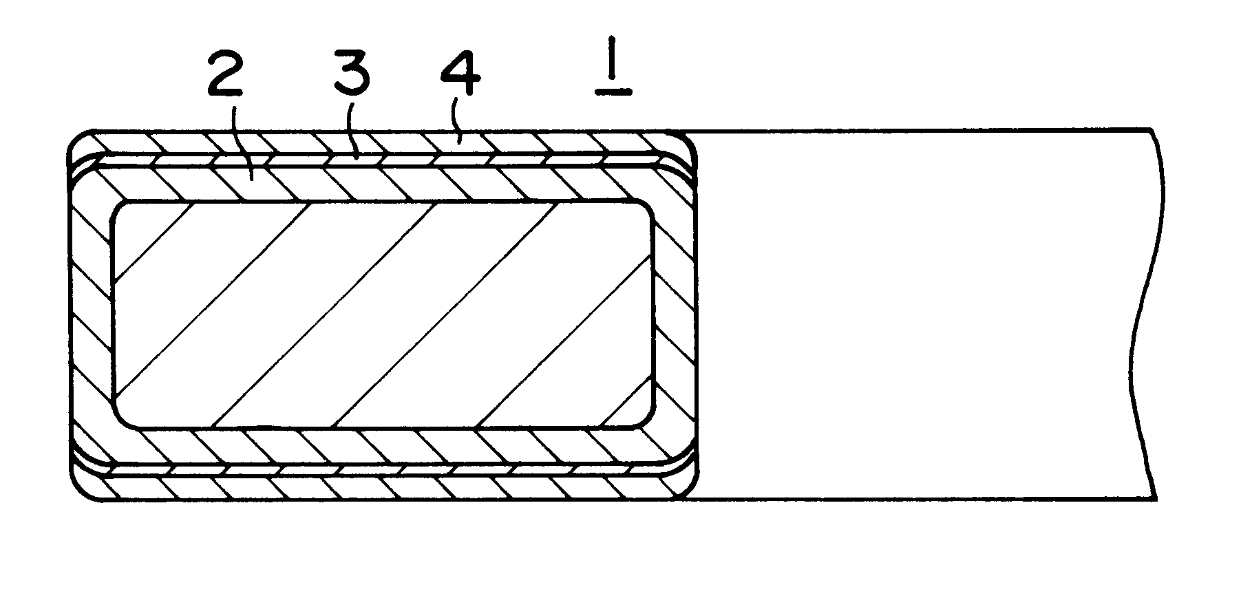
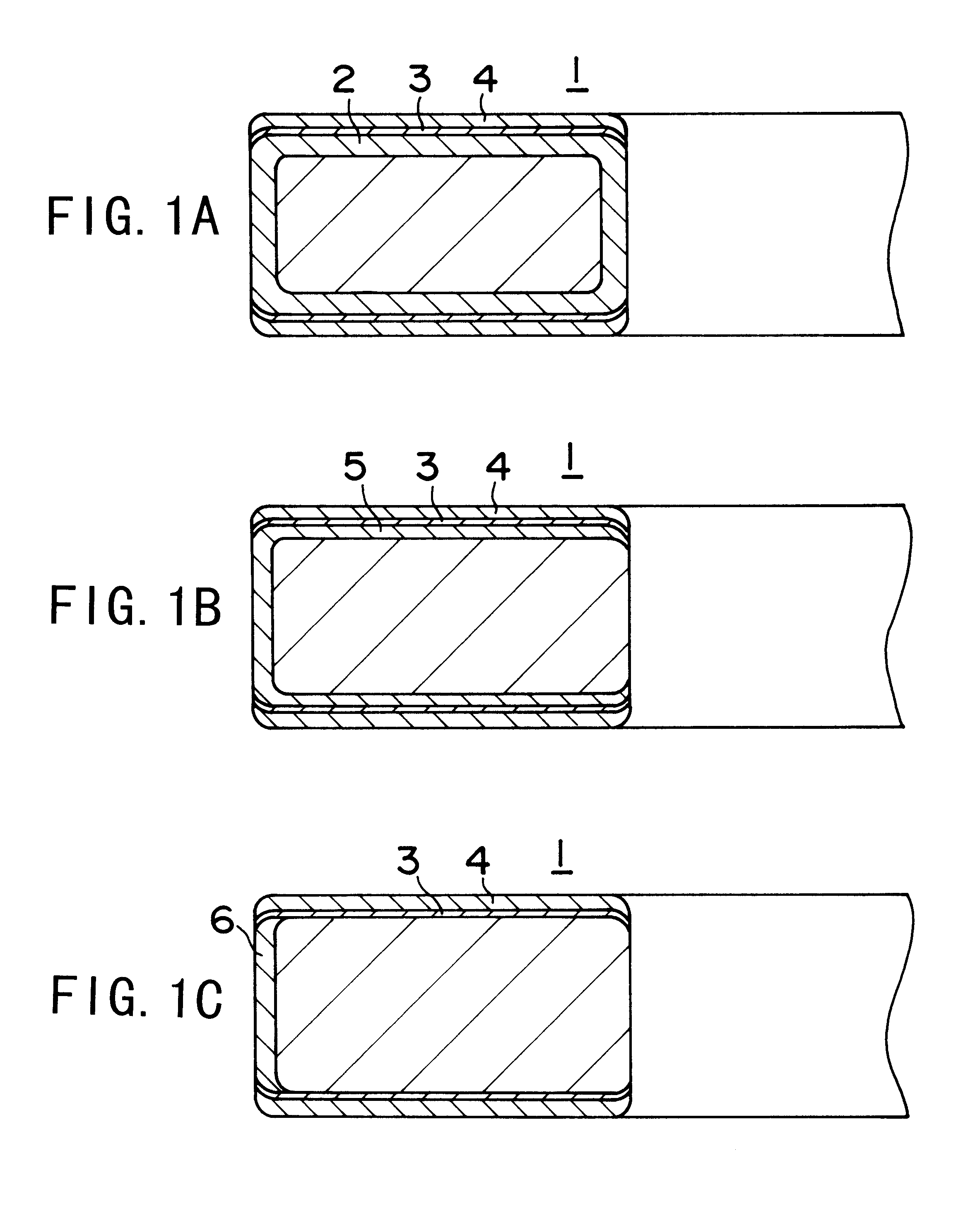
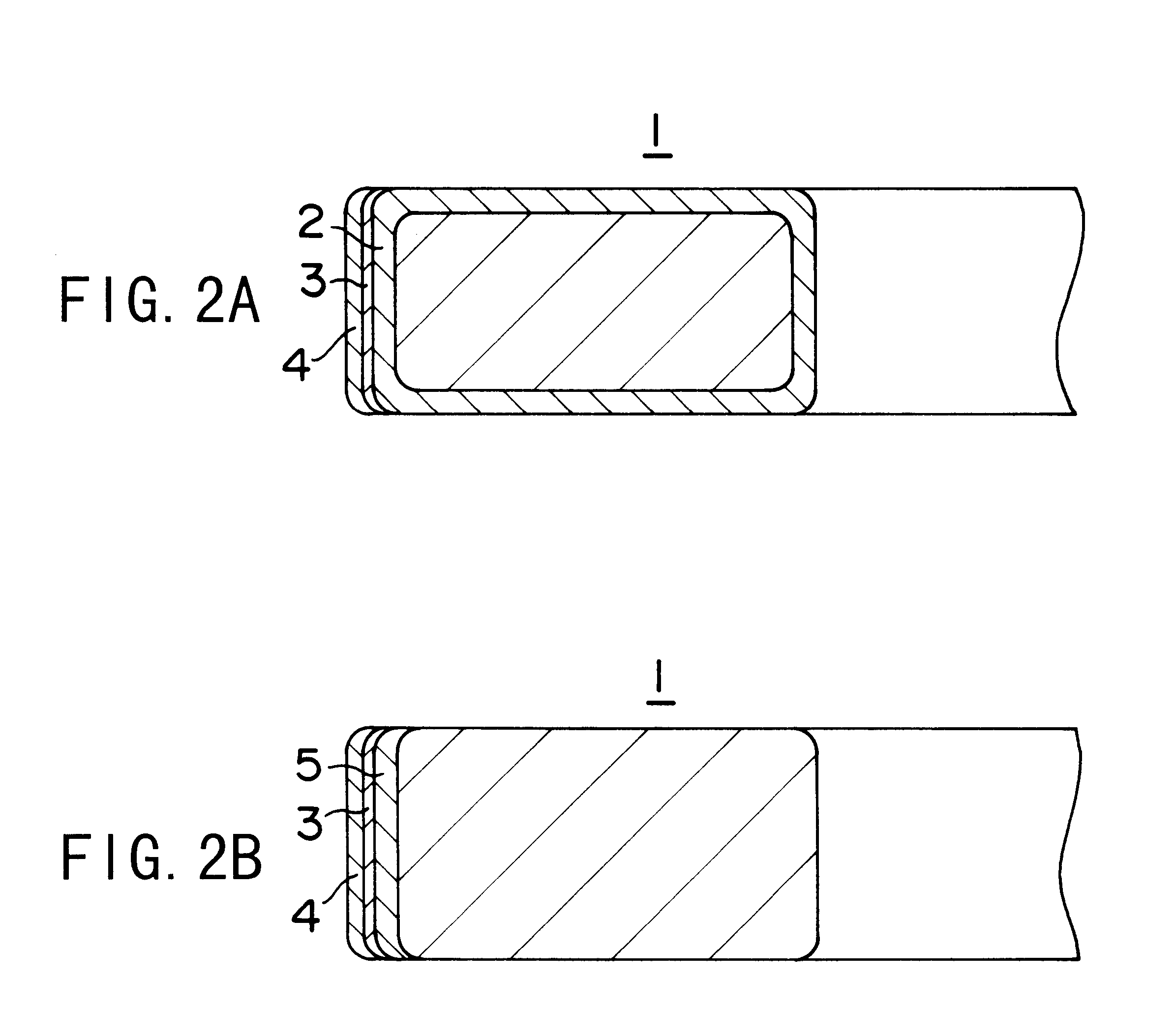
A piston ring has a diamond-like carbon film formed in a thickness of 0.5 to 30 micrometers over an under film on the upper and lower surfaces. The under film is directly formed on the surfaces, or formed on a hard surface treatment layer consisting of a gas nitrided layer or a chromium plating film. The diamond-like carbon is configured with any one of an amorphous carbon structure, an amorphous carbon structure having partly a diamond structure, or an amorphous carbon structure having partly a graphite structure. The under film is comprised of one or more elements selected from the group consisting of silicon, titanium, tungsten, chromium, molybdenum, niobium and vanadium in an atomic content of 70 percent or more and below 100 percent, and the remaining content consisting of carbon, or one or more of said elements in an atomic content of 100 percent. The films may also be formed in the same way on the outer circumferential surface of the piston ring.
Description
BACKGROUND OF INVENTION1. Technical Field of InventionThe present invention relates to a piston ring for use in internal combustion engines.2. Description of Related ArtIn recent years, engines must meet increased demands for higher output, high revolutions per minute and longer product service life and must also comply with ever stricter exhaust gas emission regulations. The piston ring must therefore function in a yet harsher operating environment. Many of such piston rings are formed typically with a hard surface treatment layer such as chromium plating film, nitrided layer or physical vapor deposition film on the upper and lower surfaces and the outer circumferential surface.However, piston rings having a nitrided layer or physical vapor deposition film are prone to wear the ring grooves of the aluminum alloy pistons. In particular, piston rings having nitrided layers are prone to cause aluminum adhesion on the upper and lower surfaces, increasing the wear on the ring grooves.In...
Claims
Login to View More Application Information
Patent Timeline
 IPC IPC(8): F16J9/26C23C14/06
CPCF16J9/26Y10S277/938Y10S277/943
Inventor IWASHITA, TAKATSUGUYAMASHITA, NOBUYUKI
Owner TEIKOKU PISTON RING CO LTD
Features
- R&D
- Intellectual Property
- Life Sciences
- Materials
- Tech Scout
- Unparalleled Data Quality
- Higher Quality Content
- 60% Fewer Hallucinations
Learn More Browse by: Latest US Patents, China's latest patents, Technical Efficacy Thesaurus, Application Domain, Technology Topic, Popular Technical Reports.
© 2025 PatSnap. All rights reserved.Legal|Privacy policy|Modern Slavery Act Transparency Statement|Sitemap|About US| Contact US: help@patsnap.com


