
Method for continuously producing expanded thermoformable materials

a technology of thermoformable materials and thermoformable materials, which is applied in the direction of manufacturing tools, applications, paper/cardboard articles, etc., can solve the problems of increased production costs, dangerous conditions, grave injuries or even death,

Inactive Publication Date: 2001-11-27
PANTERRA ENGINEERED PLASTICS +1
View PDF13 Cites 24 Cited by
  • Summary
  • Abstract
  • Description
  • Claims
  • Application Information

AI Technical Summary

Benefits of technology

Specifically, the thermoformable assembly is heated to a temperature at which the thermoformable material adhesively bonds to each mold plate. Thereafter, the thermoformable assembly is disposed between a pair of press plates, whereby the press plates engage the mold plates of the thermoformable assembly. The thermoformable material sheet, which is disposed between the mold plates, is then heated to a temperature in the range between about 50.degree. C. to 300.degree. C., preferably between 100.degree. C. to 250.degree. C., and the press plates are thereafter slowly separated so as to effect an expansion of the cross-section of the thermoformable material to the desired width. The surface of the mold plates which comes into contact with the thermoformable material may have perforations thereon, thereby creating cells in the cross-section of the expanded thermoformable material during the expansion process. Alternatively, each set of mold plates may have either the same or different diameter perforations thus enabling the creation of expanded thermoformable material having different or the same cell cross-sections.
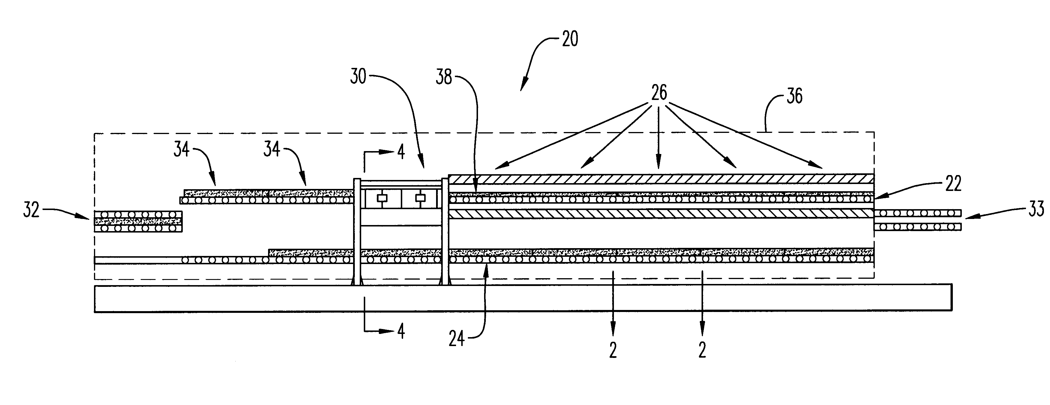
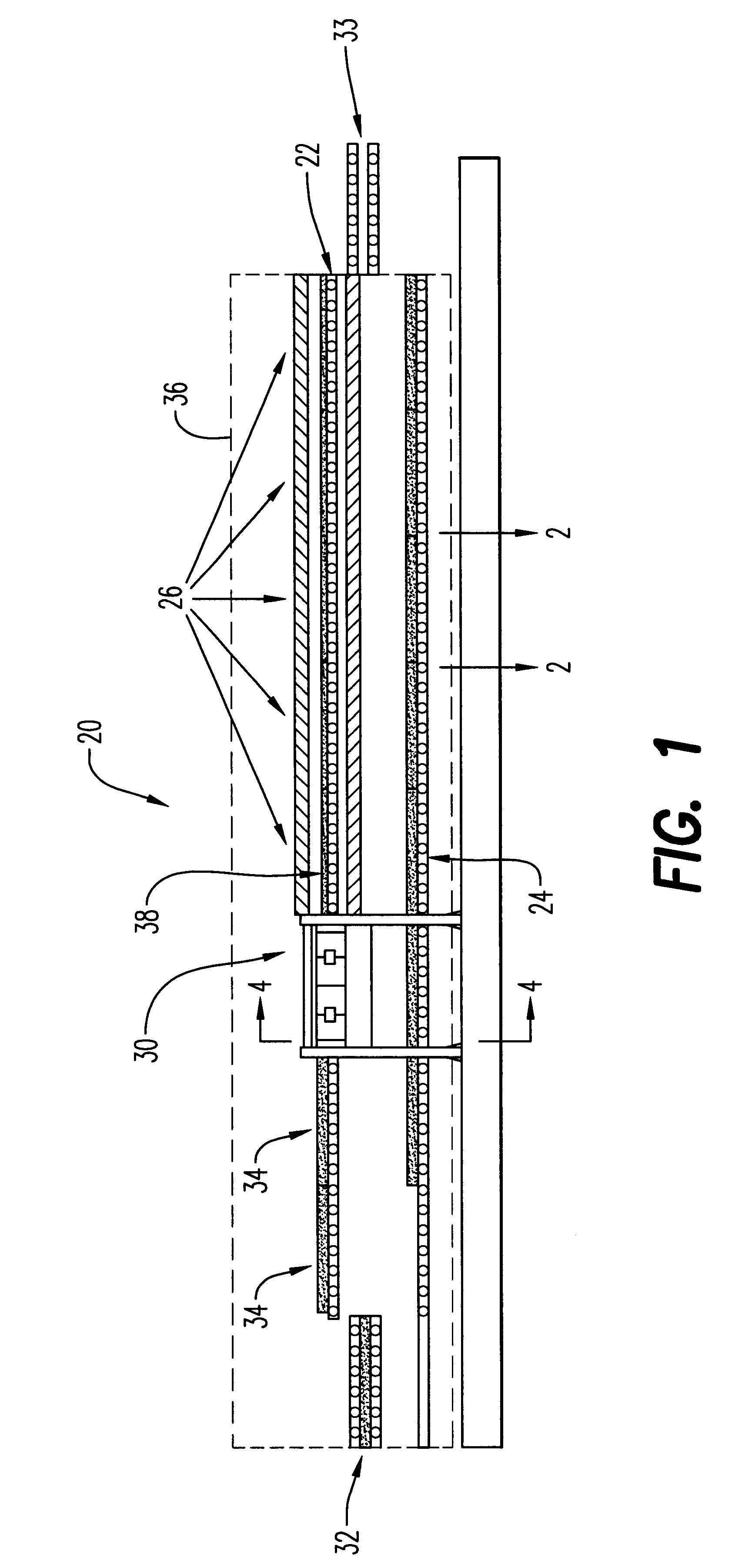
In one embodiment of the present invention, the heating, press, and cooling zones are enclosed within a housing capable of capturing heat from each individual heating, press and cooling zone, and recycling it so that heat applied to prior thermoformable assemblies can be reused to heat a subsequent thermoformable assembly, thereby conserving energy by recycling heat during operation of the continuous process.

Problems solved by technology

The problem with these processes is that the manufacturing personnel must wait approximately fifteen to twenty minutes until the expanded thermoformable material has cooled off before they can remove it from the press and insert a new thermoformable blank.
Thus, the cost of production is increased because the manufacturing personnel must wait long periods of time before each new thermoformable material blank can be inserted into the press.
Another disadvantage is that if expanded thermoformable materials with different cross-sectional geometries is desired, than the mold plates must be replaced in the press to produce the desired product.
This causes several problems.
The mold plates can be heated to temperatures in excess of 300.degree. C., which creates dangerous conditions if the manufacturing personnel are not cautious.
If they attempt to remove the mold plates before they are completely cooled off, grave injuries or even death could occur.
Thus, the cost of production is increased if a variety of expanded thermoformable materials are desired because of the additional time and precautions which the manufacturing personnel must take when replacing the mold plates.
Another disadvantage is that the thermoplastic material is heated and cooled in the same zone.
Thus, additional time is required because the thermoplastic material sheet is not pre-heated prior to its insertion into the press.
In addition, the cost of production is substantially increased because of the a mount of wasted energy in these conventional processes.
Thus, the cost of production is increased because new energy must be purchased to heat each new sheet of thermoformable material that is to be expanded and all of such energy is wasted during the cooling process.
Furthermore, another disadvantage is that the processes described above are neither automated nor continuous, and typically require multiple manufacturing personnel to produce one expanded thermoformable product.
Obviously, the use of multiple personnel greatly increases the cost of manufacturing, together with the long product cycle times and energy loss.

Method used


Image

  • Method for continuously producing expanded thermoformable materials
  • Method for continuously producing expanded thermoformable materials
  • Method for continuously producing expanded thermoformable materials

Examples


Embodiment Construction

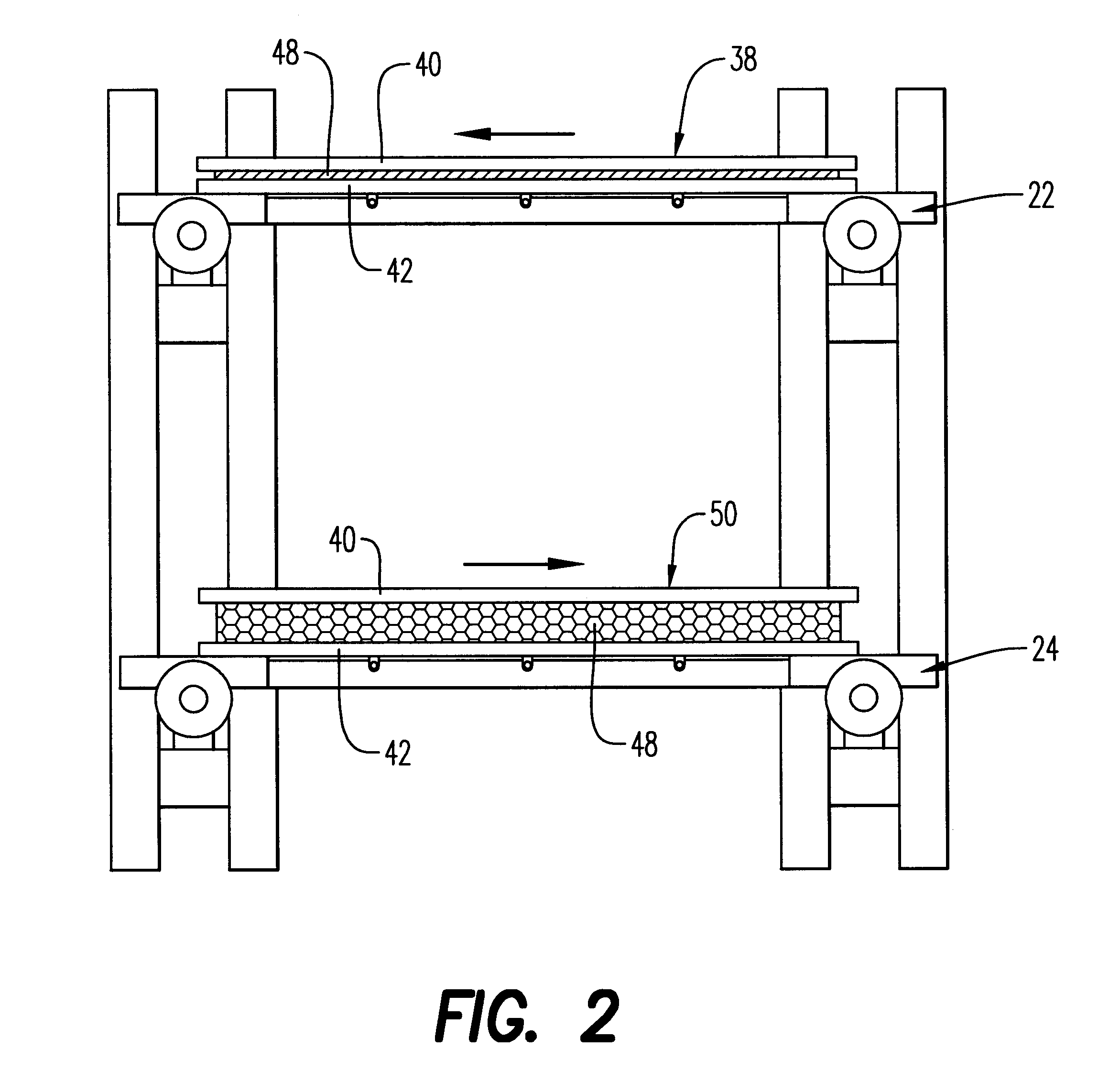
The present invention can best be described by reference to the attached figures, wherein FIGS. 1 through 5 depict the energy efficient continuous system 20 which is capable of producing expanded thermoformable material. System 20 preferably comprises a first conveyor means 22, a second conveyor means 24 enclosed within housing 36. First conveyor means 22 includes a plurality of heating zones 26, a heatable press zone 30, and a plurality of product cooling zones 34. A thermoformable assembly 38 comprising a first mold plate 40, a second mold plate 42, and a thermoformable material sheet 48 disposed therebetween is placed on a first conveyor means 22 for conveying through heating zones 26. Preferably, first mold plate 40 and second mold plate 42 are made of aluminum and are 3 to 4 millimeters in width.

As thermoformable assembly 38 is conveyed through heating zones 26, thermoformable material sheet 48 is heated to a temperature at which thermoformable material sheet 48 will adhesively...


PUM

PropertyMeasurementUnit
temperatureaaaaaaaaaa

Abstract

A method for continuously producing expanded thermoformable materials comprising the steps of: conveying a thermoformable assembly by means of a conveyor through a plurality of heating zones, whereby the thermoformable assembly is heated to a temperature at which the thermoformable material adhesively bonds to the first and second mold plates; disposing the thermoformable assembly between an upper press plate and a lower press plate, and heating the thermoformable material to a temperature in the range between about 50° to 300°C. while moving the upper and lower press plates so as to effect an expansion of the cross-section of the thermoformable material; and conveying the expanded thermoformable material through a cooling zone, wherein the expanded thermoformable material is cooled to a temperature sufficient for maintaining its structural integrity.

Description

1. Field of the InventionThe present invention relates to a method of producing expanded thermoformable materials and, more particularly, to an energy efficient method for continuously producing expanded thermoformable materials.2. Description of the Prior ArtProcesses used to make expanded thermoformable materials typically involve placing a thermoformable polymeric material blank between mold plates, which are attached to a heated press. The thermoformable polymeric material blank is heated to a temperature at which the thermoformable material will adhesively bond with the mold plates by hot tack adhesion. The mold plates are than separated apart with the thermoformable material still adhered to the mold plates so as to effect an expansion of the cross-section of the thermoformable material.Typically, the surfaces of the mold plates that are bonded to the thermoplastic material blank have a plurality of perforations thereon. The thermoplastic material will adhesively bond to the n...

Claims


Application Information

Patent Timeline
Patent Type & Authority Patents(United States)
IPC IPC(8): B29C43/20B32B3/00
CPCB29C43/203B32B3/00B32B39/00B32B38/00B29K2105/256B32B37/146Y10T156/1003B32B2309/02Y10S425/812Y10T428/24149B32B7/12B32B2519/00B32B2405/00
Inventor PHELPS, EDWIN F.
Owner PANTERRA ENGINEERED PLASTICS
Learn More