Eureka AIR delivers breakthrough ideas for toughest innovation challenges, trusted by R&D personnel around the world.

Plasma processing device, plasma torch and method for replacing components of same

a technology of plasma torch and processing device, which is applied in the direction of plasma welding apparatus, manufacturing tools, and welding apparatus, etc., can solve the problems of increasing the cost of replacement, not necessarily easy to perform tasks, and gradual wear of electrodes and nozzles

Inactive Publication Date: 2001-11-20
KOMATSU LTD
View PDF7 Cites 112 Cited by
  • Summary
  • Abstract
  • Description
  • Claims
  • Application Information

AI Technical Summary

Benefits of technology

It is a further object of the present invention to simplify the task of installing an electrode, whilst avoiding connection faults between electrical connection surfaces due to foreign matter.
The electrode can be attached and detached to and from the guide, readily, by means of the aforementioned clearance and the O-ring inserted therebetween, and furthermore, the central axes of the electrode and the guide can be aligned automatically thereby.

Problems solved by technology

In a plasma torch used for plasma arc processing, there is gradual wear of the electrode and nozzle with the passage of time during which an arc is generated.
However, since the replacing operation is carried out on the work table, this task is not necessarily easy to perform.
Therefore, compared to a standard conventional torch described previously, which does not have a cassette system, the cassette-type torch provides simpler replacement of consumable parts, but since the structure of the torch is more complex, it is significantly more expensive.
In other words, since it is necessary to ensure satisfactory electrical insulation and sealing at the connecting surfaces of the head section and base section, in order that there are no electrical insulation faults or gas or water leaks, in addition to the operation of simply connecting and separating the head section and base section, a special structure which is not required in a standard torch must be employed, and therefore, the cost thereof increases.
Consequently, in practice, cassette-type torches have not become widely used.
Therefore, if the electrode is installed in the seating whilst foreign matter, such as dirt or dust, is attached to the electrical connection surfaces, then the electrical connection surfaces will rise up due to this foreign matter and hence fail to fit together completely, leading to connection faults.
In this case, the electrical connection surfaces will generate heat and may experience melting.
There is an especially high probability of connection faults occurring in low-current types of torch which have a weak attachment force.
However, if the clearance gaps between the nozzle, electrode and insulating material are made too small, they will become difficult to fit together and take apart, when exchanging the nozzle or electrode, and hence the replacing operation is impeded.
For this reason, in the prior art, the clearances between these parts have been set to relatively large values, thus leading to problems in that the positioning accuracy of the nozzle and electrode declines as a consequence.
However, if an integrated part is used in this way, the whole part must be replaced, even if only one of the nozzle or the electrode has come to the end of its life, whilst the other is still in a usable state.
Moreover, since the insulating material, which is not a consumable item, is also replaced at the same time, there is an increase in running costs.

Method used


Image

  • Plasma processing device, plasma torch and method for replacing components of same
  • Plasma processing device, plasma torch and method for replacing components of same
  • Plasma processing device, plasma torch and method for replacing components of same

Examples


Embodiment Construction

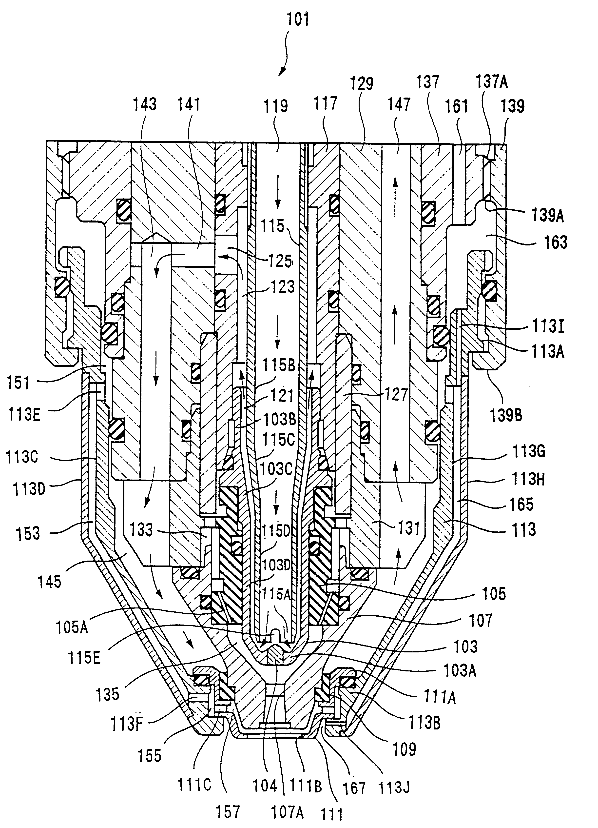
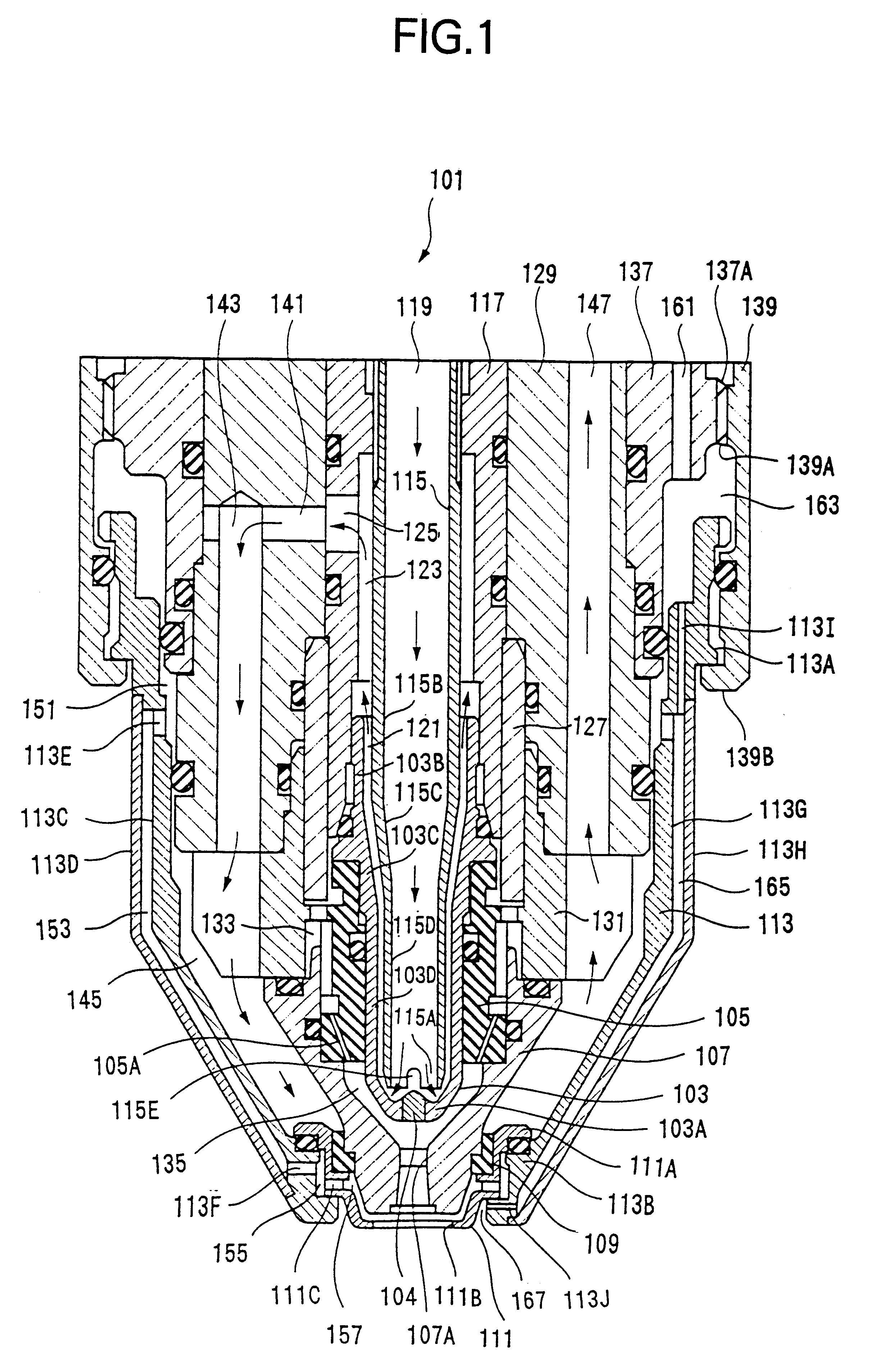
FIG. 1 is a sectional view along the central axis of a plasma torch for cutting according to a first embodiment of the present invention.

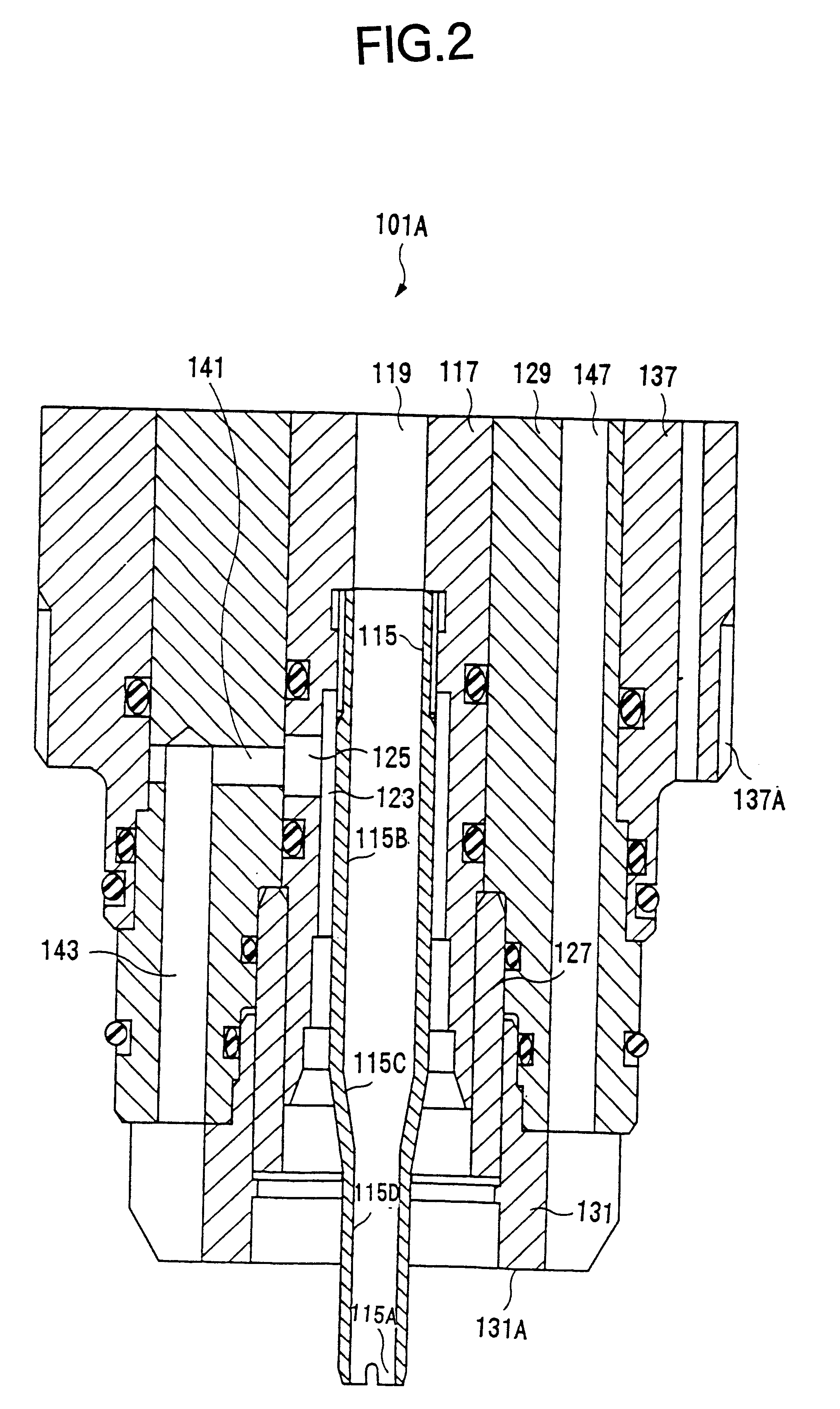
The plasma torch 101 is devised such that a cap (retainer cap) 113 constituting the outer shell of the front end portion of the torch is detached when consumable parts, such as the electrode 103, nozzle 107, and the like, are replaced. When the retainer cap 113 is detached, all of the consumable parts are detached simultaneously from the torch main unit, in a state where they are coupled to the retainer cap 113. FIG. 2 shows a sectional view of the torch main unit when the retainer cap 113 has been detached, and FIG. 3 shows a sectional view of a set comprising the retainer cap 113 and all of the parts which are detached simultaneously with the retainer cap 113.

Firstly, the overall composition of the cutting plasma torch 101 is described with reference principally to FIG. 1, also with additional reference to FIG. 2 and FIG. 3.

The plasma torch 101 i...


PUM

PropertyMeasurementUnit
swirling currentaaaaaaaaaa
insulatingaaaaaaaaaa
coupling forceaaaaaaaaaa

Abstract

The object is to facilitate replacement of consumable parts, such as the electrode, nozzle, or the like, in a plasma torch, whilst suppressing any increase in structural complexity or cost. An electrode 103, insulating guide 105 and nozzle 107 are fit together installed in a retainer cap 113. By means of O-rings 193, 195, 197, the electrode 103, insulating guide 105, nozzle 107 and retainer cap 113 are coupled together by a coupling force which allows the components to be pulled apart and separated manually. By attaching the retainer cap 113 to the torch main unit and detaching the retainer cap 113 from same, the electrode 103, insulating guide 105 and nozzle 107 can be attached and detached to and from the torch main unit, simultaneously.

Description

1. Field of the InventionThe present invention relates to a plasma processing device for performing plasma arc cutting or plasma arc welding, and more particularly, to improvements to a structure for simplifying the operation of replacing consumable parts, such as electrodes, nozzles, and the like, in a plasma torch.The present invention also relates to a plasma torch for performing cutting or welding of work by means of a plasma arc formed between an electrode and a work piece, and more particularly, to improvements in the electrical and mechanical connection structure between the electrode and torch main unit.The present invention also relates to a plasma torch wherein the accuracy of locating the position of the nozzle and electrode is improved.2. Description of the Related ArtIn a plasma torch used for plasma arc processing, there is gradual wear of the electrode and nozzle with the passage of time during which an arc is generated. In some situations, the consumable parts thereo...

Claims


Application Information

Patent Timeline
Patent Type & Authority Patents(United States)
IPC IPC(8): H05H1/26H05H1/34
CPCH05H1/34H05H2001/3478H05H1/3478
Inventor YAMAGUCHI, YOSHIHIROKURAOKA, KAZUHIRO
Owner KOMATSU LTD
Why Eureka
Eureka Blog
Learn More