
Polarization insensitive semiconductor optical amplifier

a semiconductor optical amplifier and polarization-independent technology, applied in semiconductor lasers, laser optical resonator construction, laser details, etc., can solve the problems of polarization dependence/sensitivity, and attenuation of optical signals

Inactive Publication Date: 2001-10-30
II VI DELAWARE INC
View PDF2 Cites 47 Cited by
  • Summary
  • Abstract
  • Description
  • Claims
  • Application Information

AI Technical Summary

Problems solved by technology

A particular problem in optical communications is attenuation of the optical signal.
The attenuation may occur due to transmission of the signal, distribution of the signal, and losses due to insertion of components in the transmission path.
Polarization dependence / sensitivity (TE / TM differential gain) is another problem for optical networks.
This causes problems in the network because it causes signal levels to change with time in an uncontrollable manner, particularly when several of these devices are cascaded in series.
One particular problem with SOAs is that they are inherently polarization sensitive asymmetrical structures.
Thus, it is very difficult to eliminate polarization dependent gain (loss) from SOAs.
However, these attempts at an on-chip solution are difficult to manufacture and have had limited success.
It is very difficult to correct for polarization dependent gain because of the very precise thickness control and precise strain control required when manufacturing SOAs.
The prior art is not able to control the semiconductor processing steps to the extent necessary to produce SOAs having less than 1 dB polarization sensitivity.
Furthermore, the SOAs need to be polarization insensitive at all wavelengths and at all operating currents and that adds additional complexity to the design and semiconductor processing.

Method used


Image

  • Polarization insensitive semiconductor optical amplifier
  • Polarization insensitive semiconductor optical amplifier
  • Polarization insensitive semiconductor optical amplifier

Examples


second embodiment

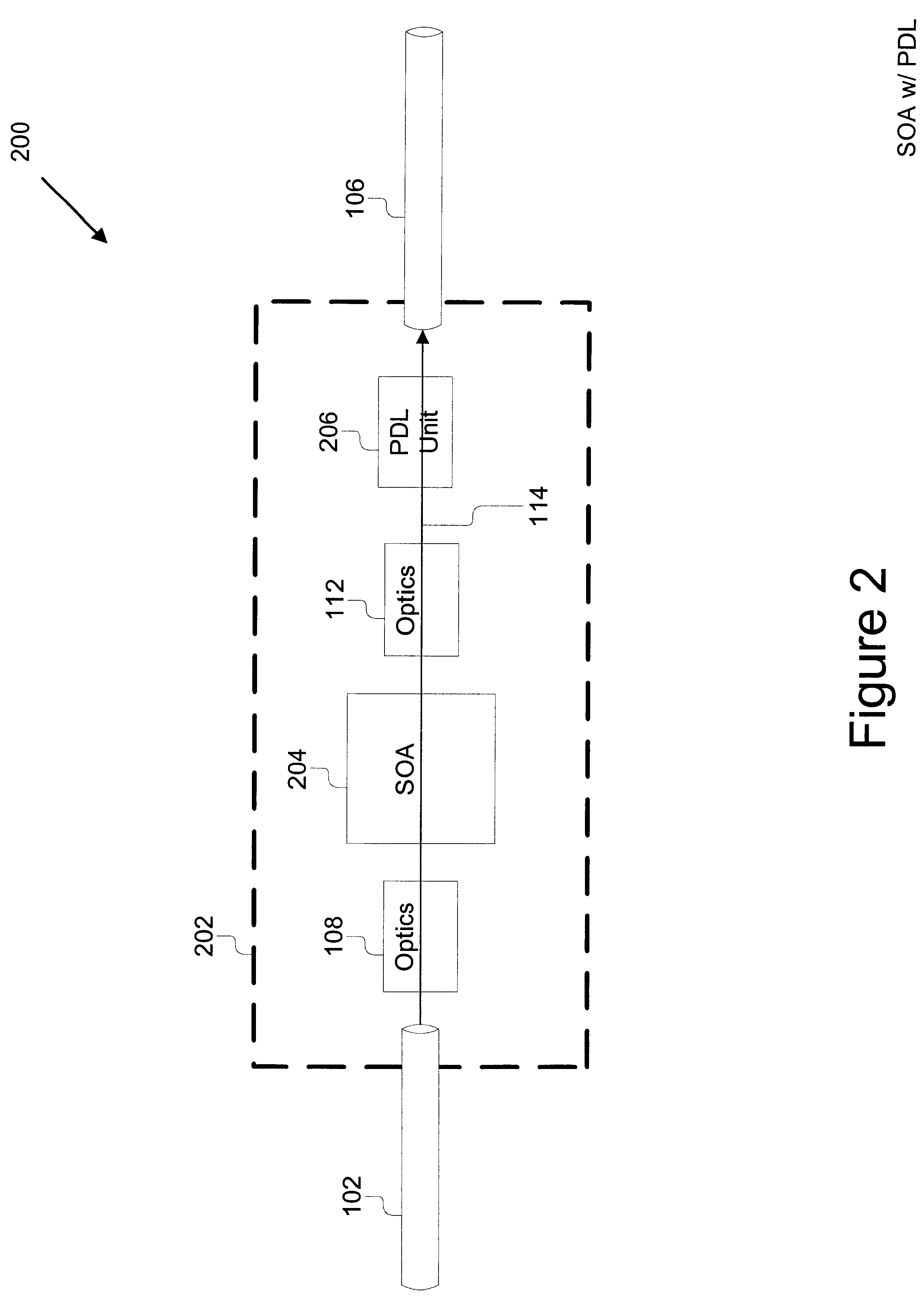
Referring now to FIG. 7, a second embodiment for the PDL unit 206b is shown. The PDL unit 206b provides polarization dependent loss using a polarizer 704. The PDL unit 206b preferably comprises a first lens 702, a polarizer 704 and a second lens 706. The first and second lenses 702, 706 are provided to optically couple the polarizer 704 with the SOA 204 and the fiber 106, respectively. Those skilled in the art will recognize that the second lens may be eliminated because it is redundant with the optics 112. The polarizer 704 is preferably a parallel-metallic-strip polarizer. Such polarizers are generally described in p. 14-24 of the Melles Griot catalogue titled "Optics Guide 5", copyright 1990. Such parallel-metallic-strip polarizers are formed using thin film technology. In contrast to the prior art, however, the polarizer 704 used in the present invention is modified to provide only a minimal or needed amount of rejection. This can be accomplished by increasing the distance, d, b...

fifth embodiment

FIG. 10A is a block diagram of a fifth embodiment for a polarization dependent loss unit 206e attached to a preferred embodiment for the SOA 204a. In this embodiment, the PDL unit 206e takes the form of a coating added to the SOA chip 204a. A preferred embodiment of the SOA chip 204a is shown in FIG. 10A. The SOA chip 204a preferably has a "tilted stripe" 1002. The SOA stripe 1002 is preferably tilted on the wafer 1004 by 7 to 12 degrees, .phi., from the cleave planes 1006 in order to prevent lasing. As the TE and TM signals leave the SOA chip 204a on the output end, some of the light reflects from the semiconductor / air interface, and is lost. This loss is polarization dependent. Thus, depending on the coating 206e applied to the output end of the SOA chip 204a, the polarization dependence can be adjusted. The PDL unit 206e is preferably a coating of Aluminum-Nitride film, but could be any film used for anti-reflection coating the facets, including multiple-layer films utilizing two...


PUM


Abstract

An optical amplifier module that is insensitive to polarization comprises a first fiber, a second fiber, a semiconductor optical amplifier (SOA), and a polarization dependent loss (PDL) unit. The first fiber provides for optical input to the SOA. The SOA amplifies the optical signal received and outputs the amplified signal. The output of the SOA is optically coupled to the unit. The PDL unit provides polarization dependent loss and the loss is preferably selected to match the polarization dependent gain of the SOA such that when two are coupled there is no overall polarization dependence. The output of the PDL is optically coupled to the fiber for transmission output. The present invention also comprises a method for manufacturing an optical amplifier module that comprises the steps of: determining the polarization dependent gain of an SOA, determining the polarization dependent loss of a plurality of PDL units, selecting a PDL unit such that the polarization dependent loss when coupled to the SOA is reduced, and packaging the SOA and the PDL unit as an optical amplifier module.

Description

1. Field of the InventionThe present invention relates to optical communications systems. More particularly, the present invention relates to polarization independent optical amplifiers. Still more particularly, the present invention relates to a method for packaging semiconductor optical amplifiers that eliminates polarization dependence.2. Description of the Background ArtOptical communications systems are rapidly becoming a widespread and dominant technology in telecommunications and networking. Optical communications systems transmit information optically at very high speeds over fiber optics. The basic components of an optical communications system include: an optical transmitter; fiber optics, and an optical receiver. An optical transmitter incorporates information to be communicated into an optical signal and sends the optical signal. Fiber optics carries the optical signal over a distance. Finally, the optical receiver receives the optical signal and recovers the information...

Claims


Application Information

Patent Timeline
IPC IPC(8): H01S5/50H01S5/00H01S5/10
CPCH01S5/5009H01S5/1085
Inventor WALKER, JEFFREY D.DIJAILI, SOL P.RATOWSKY, RICHARD P.
Owner II VI DELAWARE INC
Learn More