
Fluid-insulated electrical link device

Inactive Publication Date: 2001-10-30
SILEC CABLE
View PDF10 Cites 27 Cited by
  • Summary
  • Abstract
  • Description
  • Claims
  • Application Information

AI Technical Summary

Benefits of technology

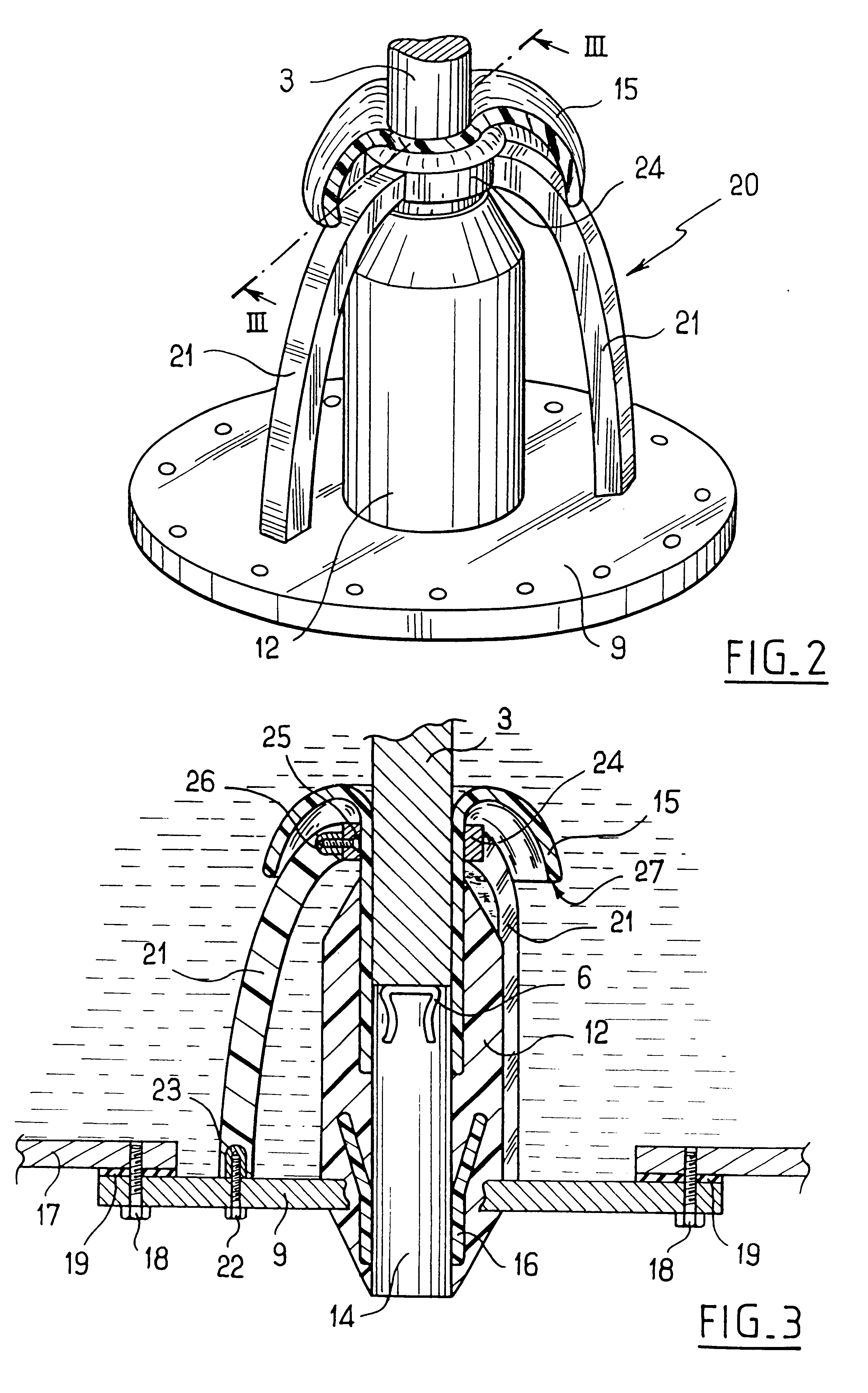
The pluggable connection member is thus surrounded by the insulating fluid contained inside the enclosure, thereby minimizing the electric stresses in the material surrounding the pluggable connection member. In addition, the device of the invention can be fully assembled and filled with fluid in a workshop such that when an electricity cable is put into place on site, all that needs to be done is to prepare the end of the cable and engage it in the insulating sleeve so as to plug the cable conductor without any leakage from the enclosure, thus making it possible to avoid handling the fluid on site.
In an advantageous version of the invention, the deflector extends on both sides of the wall of the enclosure through which the insulating sleeve passes. This minimizes the size of the link device of the invention without harming electric field distribution.

Problems solved by technology

Such an electrical link device is the seat of high levels of electric stress when it is used at very high voltage.
In addition, since that device does not have any electric field-distributing member, it is necessary to provide a separate stress-reducing member which is mounted on the electricity cable prior to it being put into position, thus requiring manipulation to be performed to avoid electric stresses appearing at the interface between the inside surface of the insulating sleeve and the field-distributing member, which manipulations are difficult to perform on site.

Method used


Image

  • Fluid-insulated electrical link device
  • Fluid-insulated electrical link device
  • Fluid-insulated electrical link device

Examples


Embodiment Construction

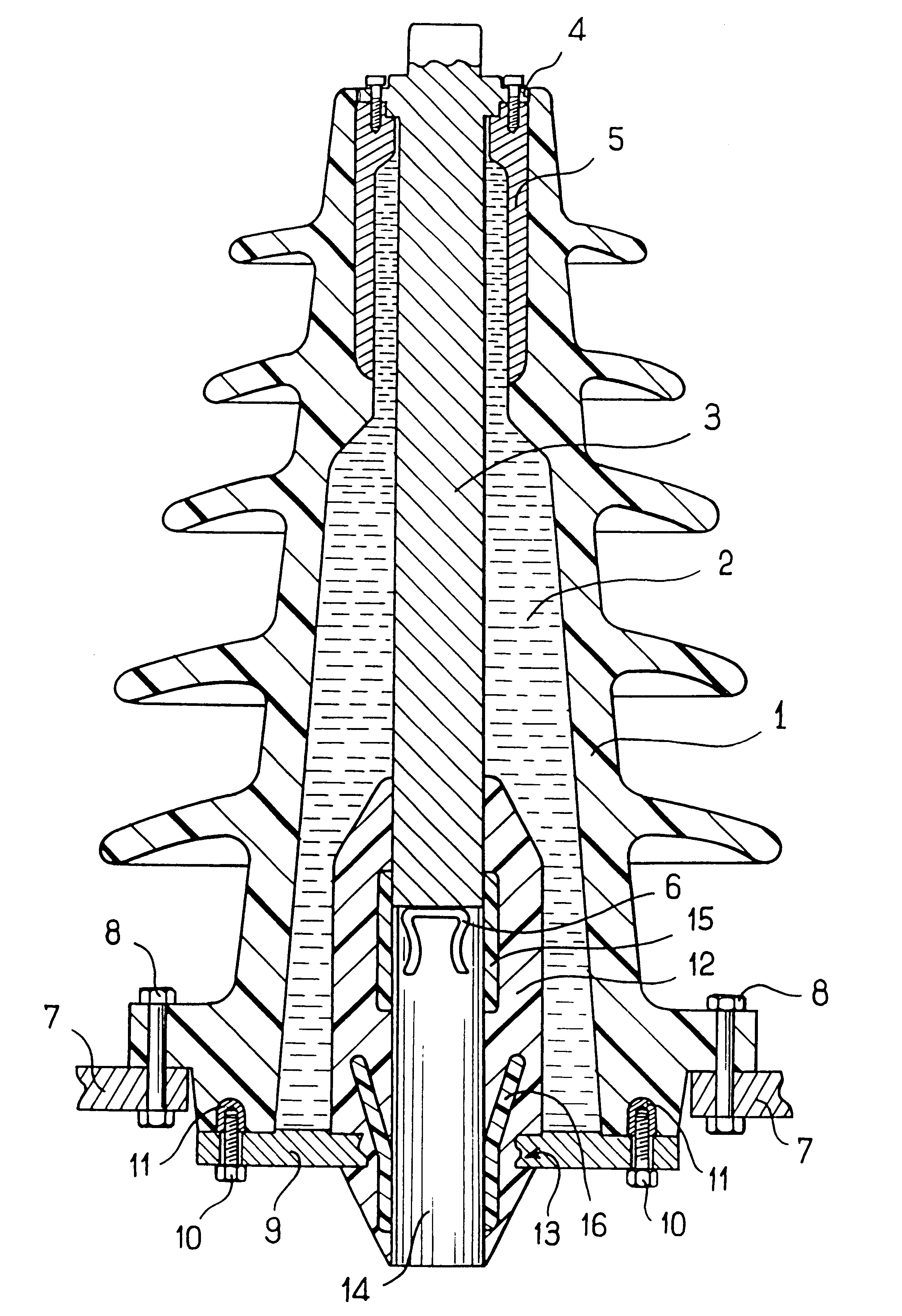
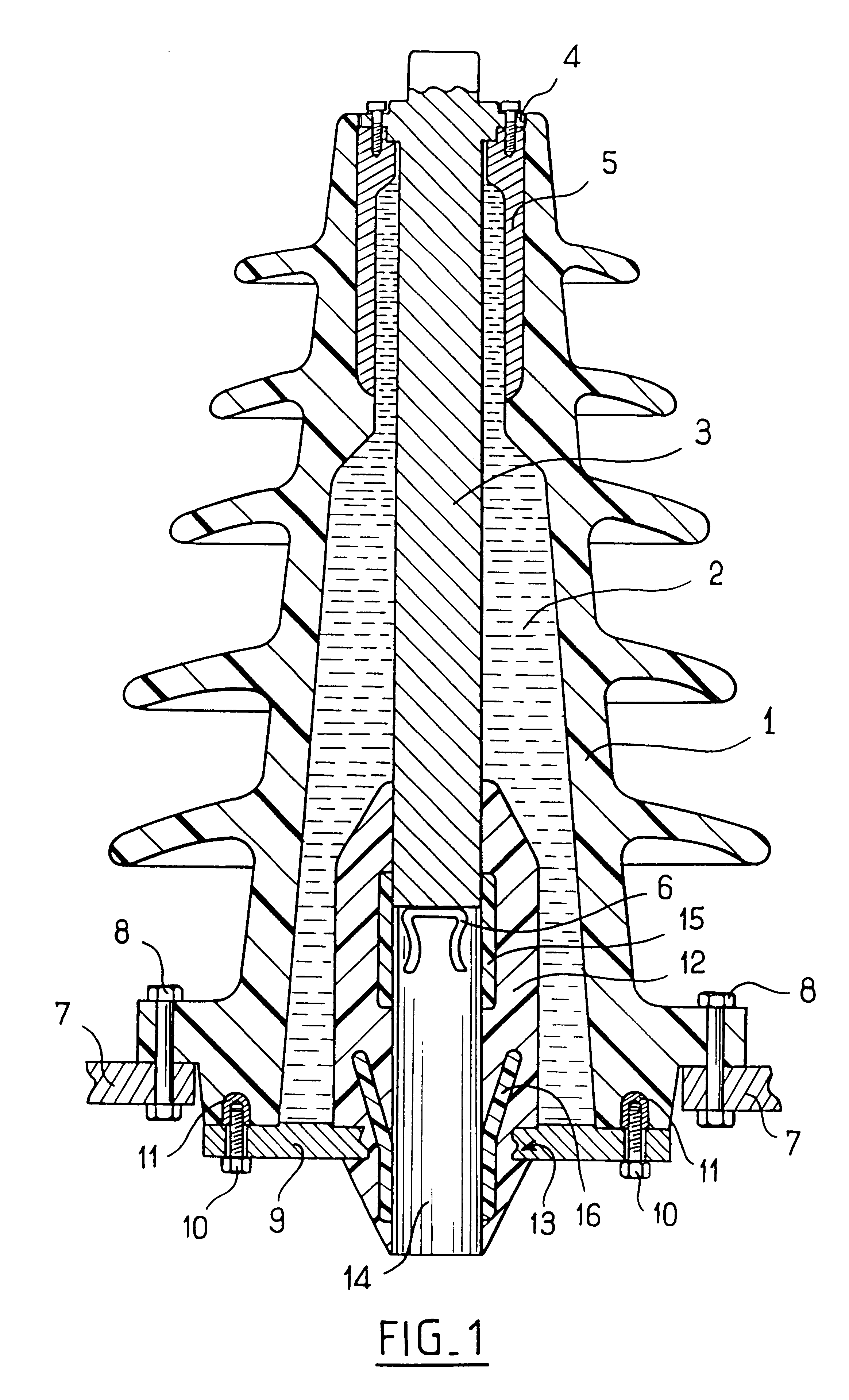
With reference to FIG. 1, the electrical link device of the invention is described in the context of an outdoor unit type device, i.e. the enclosure is constituted in part by an insulator 1, e.g. an insulator made of porcelain or of fiberglass-reinforced epoxy resin, and having outwardly-projecting skirts or "sheds". At its bottom end, the insulator 1 is fixed in conventional manner on a support 7 by bolts 8, and is closed by a metal plate 9 which is fixed by means of screws 10 that co-operate with inserts 11 embedded in the wall of the enclosure. Sealing between the plate 9 and the side wall of the insulator is preferably ensured by an O-ring (not shown).

A metal link bar 3 extends inside the enclosure and is fixed in leakproof manner thereto. To this end, the conductive link bar 3 has a collar 4 which is fixed by means of screws to a metal insert 5 that is embedded in the wall of the insulator. Preferably, an O-ring (not shown) is disposed between the collar 4 and the metal insert ...


PUM


Abstract

The electrical link device comprises an enclosure (1, 9) containing a fluid insulator (2), a conductive link bar (3) disposed inside the enclosure and having one end fixed in leakproof manner to an insulating elastomer sleeve (12) that passes through the wall of the enclosure in leakproof manner, the link bar (3) being connected inside the enclosure to a pluggable connection member (6) surrounded by a conductive screen (15), the elastomer sleeve (12) also including a conductive deflector (16) flush with the inside surface of the insulating sleeve at a distance from the conductive screen (15).

Description

The present invention relates to a fluid-insulated electrical link device enabling a high voltage electricity cable to be connected to a metal-clad unit or to an outdoor unit.Document EP-A-148 394 discloses an electrical link device for a metal-clad unit, where the device is insulated by means of a fluid such as sulfur hexafluoride in gaseous form. The electrical link device described in that document has a conductive link bar placed inside the enclosure with one end fixed in leakproof manner to a sleeve of insulating resin that passes in leakproof manner through the wall of the enclosure that contains the insulating gas. The link bar extends outside the enclosure and is connected to a pluggable connection member disposed in the portion of the sleeve that extends outside the enclosure and that is surrounded by a conductive screen forming a Faraday cage around the pluggable connection member.Such an electrical link device is the seat of high levels of electric stress when it is used ...

Claims


Application Information

Patent Timeline
IPC IPC(8): H01B17/00H01B17/34H01R13/53
CPCH01B17/34H01R13/53
Inventor ARGAUT, PIERRE
Owner SILEC CABLE
Learn More