
Gear transmission with stepless adjustable translation

Inactive Publication Date: 2001-10-30
BERGER MATTHIAS
View PDF8 Cites 6 Cited by
  • Summary
  • Abstract
  • Description
  • Claims
  • Application Information

AI Technical Summary

Benefits of technology

Therefore it is an object of the invention to furnish a mechanical gear transmission with continuously changeable transmission ratio with an as uniform as possible transmission of the rotary motion of the drive shaft to the driven shaft and with as low as possible wear appearances at the function determining contact faces, in particular of the driven side gear transmission part system. The reliability of the overall system is to be improved thereby and the maximum operational life of the overall system is to be increased. In addition the mechanical drive working with a stepwise driving member should be suitable for a stepless rotation speed or, respectively, torque conversion for application within a large region of mechanical power to be transferred. The overall system in addition should be free of slippage and should operate with a high degree of effectiveness.
The material load of the gear transmission elements based on friction is substantially less in the gear transmission construction according to the present invention, wherein a cam gear performs the transformation of the translated uniform translation motion into the uniform rotary motion of the driven shaft, because the friction occurs here in particular as a roller friction, wherein the roller friction is by orders of magnitude smaller as compared with the sliding friction by motion transfer through gear rack / gear wheel in the above recited gear transmission systems. The material abrasion or, respectively, the wear, is reduced and the mode of operation of the overall gear transmission with respect to uniformity of its courses of motion is improved and the useful life of the overall gear transmission is increased.

Problems solved by technology

The required friction between the friction wheels can only be achieved by large press-on forces.
The large press-on forces require however high loads of material at the two contract points or, respectively, contact lines and represent a substantial load for the bearings and the drive shafts.
In addition, friction wheel gear transmissions are associated with a substantial slippage, which slippage again results in a decreased degree of effectiveness of the arrangement.
The hydraulic transmissions are to a large extent associated with slippage and require high expenditures.
Similarly electrical stepless transmissions are only suitable for special application purposes because of the not inconsiderable plant expenditures and therefore are not to be considered further in this context.
The still present nonuniformity of the rotary motion can cause substantial load peaks and thereby causes a high wear and a low lifetime of the transmission gear.
The results of these solutions however are either not satisfactory, not sufficient wear resistant or they require a high constructive expenditure.
A substantial deficiency of these transmission gear systems comprises that the wear appearances occur with the transformation of the translational motion of the gear rack into the rotary motion of the gear wheel, wherein the wear appearances are caused in particular by the sliding friction effects, are of substantial size especially in continuous operation and thus can substantially interfere with the reliability of the overall gear transmission.
The strong and in particular nonuniform wear at the function determining contact faces of the gearing entails deviations from the desired relative motion of the drive means, which in turn are the cause for a rapidly progressing wear process.
In addition there is generated a nonuniformity in the running of the gear transmission with the frequency of the gearing teeth engagement, because flank regions of each tooth wear off nonuniformity, wherein the wear processes are most pronounced at the foot of the tooth.
The recited disadvantages decrease the reliability and the operational life of such gear transmission systems substantially.

Method used


Image

  • Gear transmission with stepless adjustable translation
  • Gear transmission with stepless adjustable translation
  • Gear transmission with stepless adjustable translation

Examples


Embodiment Construction

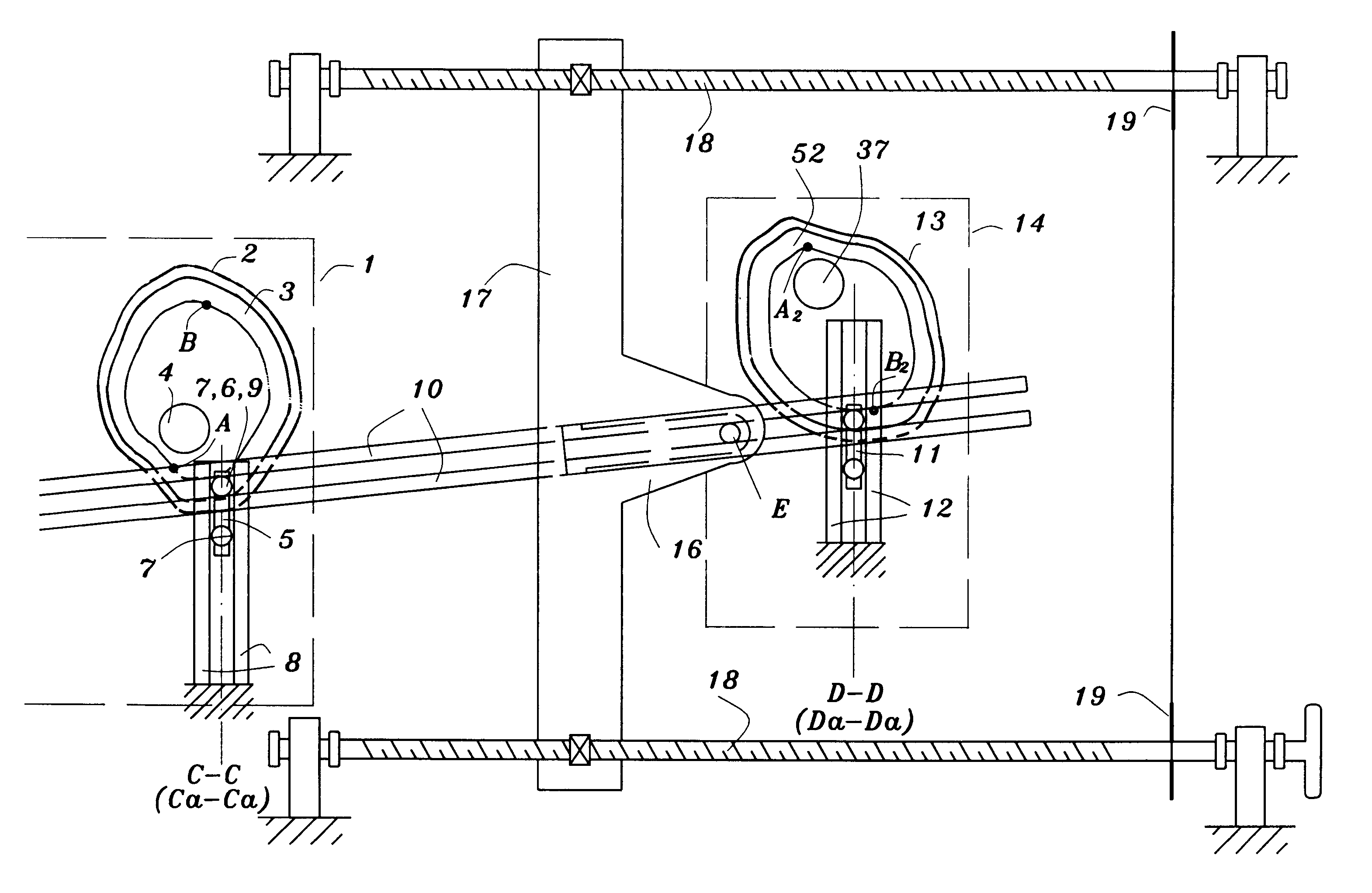
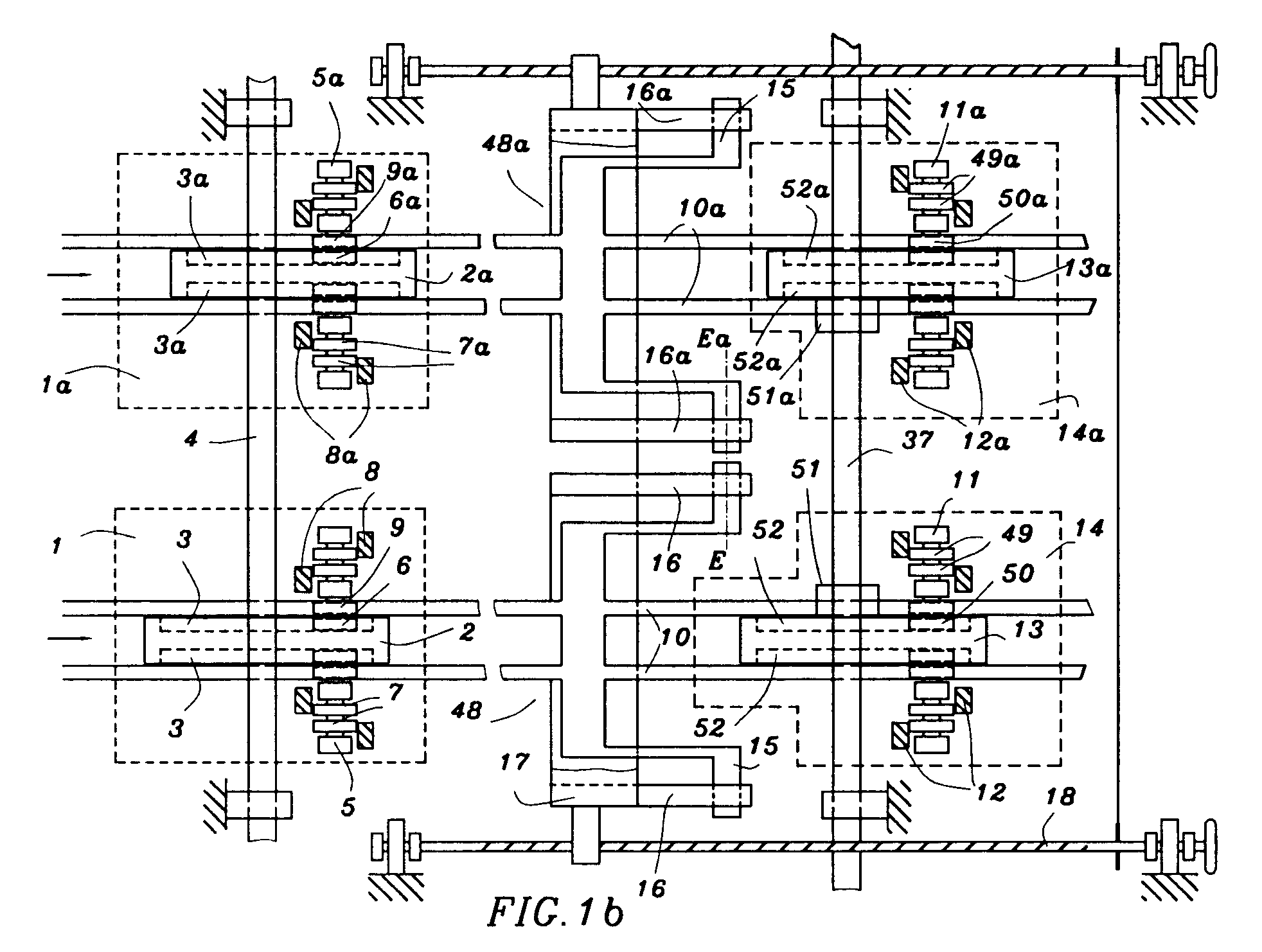
The gear transmission according to the present invention is schematically illustrated in the FIGS. 1a and 1b, wherein two gear transmission I, II units of the gear transmission are disposed axially next to each other. However, FIG. 1a shows only one of the two, equally constructed gear transmission units for purposes of surveyability. A planar cam gear transmission with a cam disk as a cam member 2 is employed as a first force transmission means 1, wherein the cam disk is furnished on two sides with a groove curve 3. The cam member is connected to the drive shaft 4 fixed against rotation. The curve flank of the groove curve exhibits the form of an involute of a circle in the load region, which load region is the region between the position A and position B in the figure while the disk is rotating in the right direction. The region of the curve flank to be understood as the load region, which region of the curve flank serves for the force transmission during constant translation rati...


PUM


Abstract

The invention relates to a gear transmission with a steplessly adjustable translation ratio for converting of rotary speeds and of torques of shafts. The uniform rotary motion of a drive shaft is transferred to a driven shaft with the aid of time staggered operating gear transmission units. The rotary motion is transformed by a cam transmission initially into a uniform translational motion and in the following this uniform translational motion is transformed into another, also uniform translational motion, with a speed depending on the translation ratio setting with a translation device. Finally this translational motion is transferred again into a uniform rotary motion by a further planar cam transmission and transferred to the driven shaft.

Description

1. Field of the InventionThe invention relates to a gear transmission with stepless adjustable translation ratio for converting rotational speeds and torques between two shafts.2. Brief Description of the Background of the Invention including Prior ArtSuch converters are employed in the complete drive technology, in particular with machine tools and drives for vehicles.Motors depend in their mechanical power on the rotation speed. Motors operate usually in their most economic region of rotation speed under favorable energy use or in the region of maximum delivered power. In contrast the driven machines are to exhibit different rotation speeds depending on their use or, respectively, their operating state in each case. The rotation speeds of drive unit and driven machine are adapted to each other by gear change boxes with corresponding transmission ratios. The loss in motor power can be kept small upon optimum setting of the transmission ratio. An optimum transfer of the rotary motio...

Claims


Application Information

Patent Timeline
IPC IPC(8): F16H29/00F16H29/20F16H29/08
CPCF16H29/08F16H29/20Y10T74/1836Y10T74/1527Y10T74/1513Y10T74/1523Y10T74/165Y10T74/1828Y10T74/2107
Inventor BERGER, MATTHIAS
Owner BERGER MATTHIAS
Learn More