
Hydraulic control system for continuously variable transmission

a technology of continuously variable transmission and hydraulic control system, which is applied in the direction of gearing control, gearing elements, gearing bearings, etc., can solve the problems of abnormal shock, adverse effect of forward clutch and the like, burning in the reverse brake,

Inactive Publication Date: 2001-10-23
SUBARU CORP
View PDF21 Cites 34 Cited by
  • Summary
  • Abstract
  • Description
  • Claims
  • Application Information

AI Technical Summary

Benefits of technology

It is a further object of the present invention to provide a hydraulic control system having a reverse brake of small size with an adequate torque capacity.

Problems solved by technology

This type of hydraulic control system has a defect in that the variation of the line pressure caused by the fluctuation of engine torque or accompanied by the speed ratio control may affect the operation of the forward clutch and the like adversely.
On the other hand, in a case where a driver moves the select lever to the reverse range inadvertently during running forwardly, the reverse brake is engaged before the forward clutch is released and an "interlocking" phenomenon occurs between the forward clutch and the reverse brake, this incurring an abnormal shock or leading to a burning in the reverse brake.
However, this restrictor has an adverse effect in that when the select lever is placed from the neutral (N) position to the reverse (R) position under the state of idling, a driver may feel some degree of delay in the vehicle starting due to the delay of the engagement of the reverse brake.

Method used


Image

  • Hydraulic control system for continuously variable transmission
  • Hydraulic control system for continuously variable transmission
  • Hydraulic control system for continuously variable transmission

Examples


Embodiment Construction

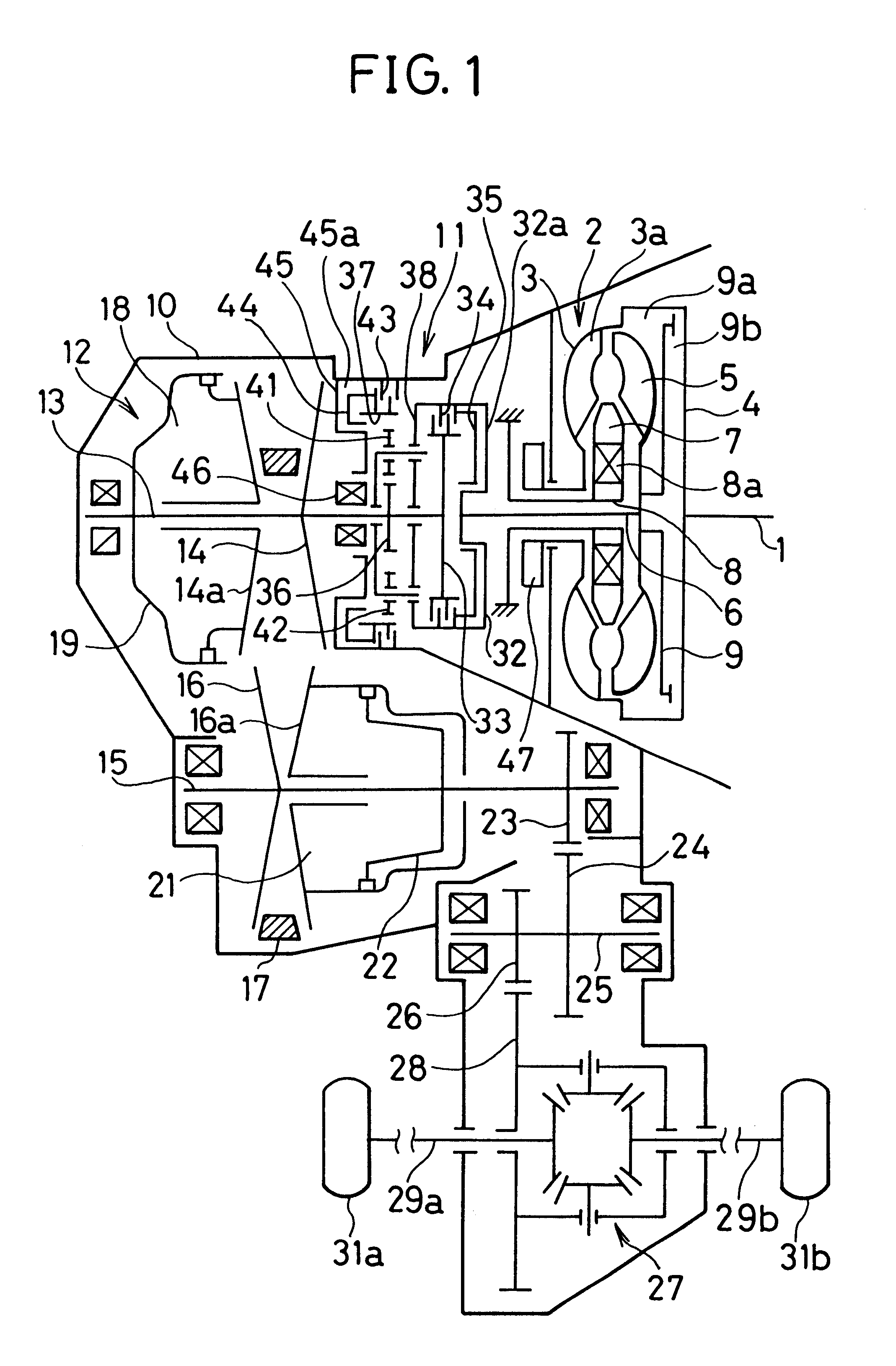
Referring first to FIG. 1, a crankshaft 1 driven by an engine (not shown) is directly connected with a pump impeller case 3 of a torque converter 2 through a drive plate 4. A pump impeller 3a provided in the pump impeller case 3 is opposed to a turbine runner 5 directly connecting to a turbine shaft 6. There is provided a stator 7 between the pump impeller 3a and the turbine runner 5 and the stator 7 is supported by an one-way clutch 8a which is fixed to a stator supporting shaft 8. Further, a lockup clutch 9 is directly connected with the turbine shaft 6 so as to engage and disengage with the drive plate 4. Thus, the engine power is transmitted to the turbine shaft 6 through the torque converter 2 or the lockup clutch 9.

A chamber on the left side of the lockup clutch 9 is so-called "apply chamber" 9a and a chamber on the right side thereof is so-called "release chamber" 9b. When the working fluid supplied to the release chamber 9b is circulated in the supply chamber 9a, the torque ...


PUM


Abstract

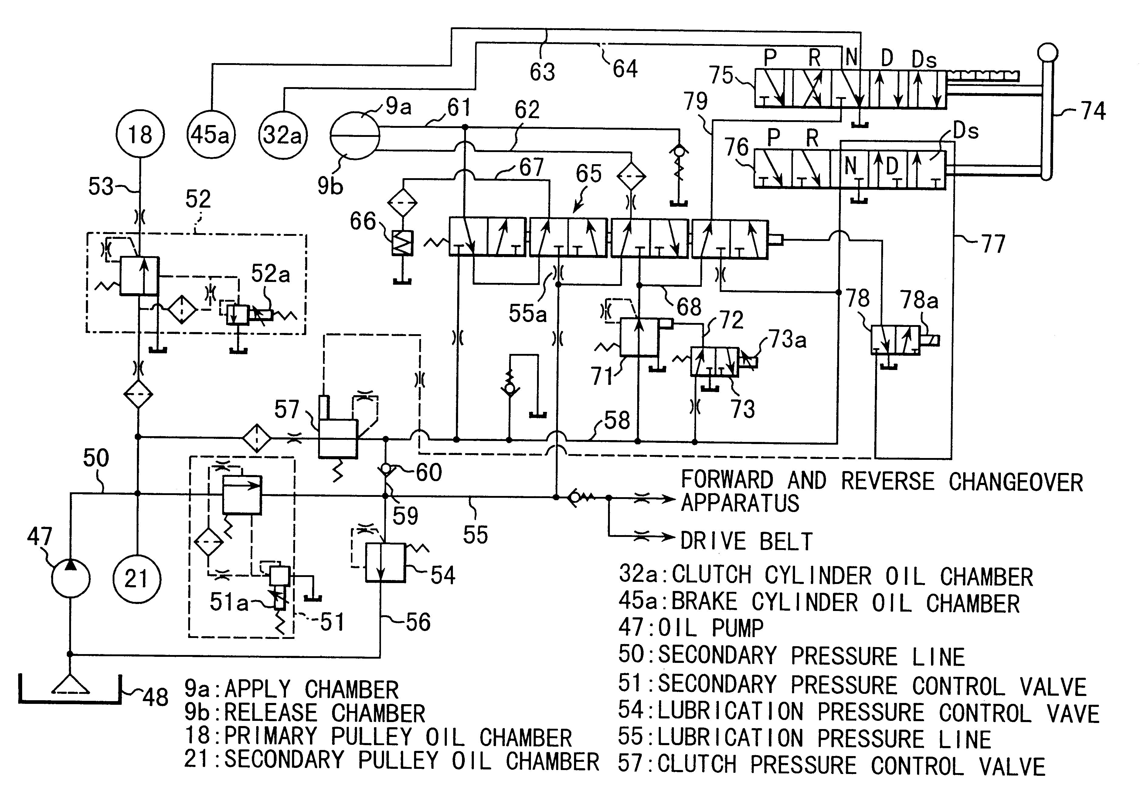
Hydraulic pressure generated by an oil pump driven by an engine is regulated to a secondary pressure by means of a secondary pressure control valve. The secondary pressure is employed for controlling a secondary pulley and a primary pulley. On the other hand, the secondary pressure is reduced to a clutch pressure by means of a clutch pressure control valve. The communication between an apply chamber and a release chamber of a torque converter, oil chambers of actuators for a forward clutch and a reverse brake of a forward and reverse changeover apparatus and a clutch pressure line and a lubrication pressure line are controlled by means a switching valve. The clutch pressure is regulated to a high clutch pressure and to a low clutch pressure, respectively by controlling reverse signal pressures supplied to these outer pilot chambers. Thus, respective hydraulic controls for the pulleys, the lockup clutch and the forward and reverse changeover apparatus can be performed independently by use of a single hydraulic pressure source.

Description

1. Field of the InventionThe present invention is related to a hydraulic control system for a vehicular continuously variable transmission and, more particularly to a hydraulic control system for controlling a forward and reverse changeover apparatus and a lockup clutch incorporated in the continuously variable transmission.2. Discussion of the Prior ArtsThere is known a belt-and-pulley type continuously variable transmission whose speed ratio is continuously variable. The continuously variable transmission comprises a power transmission mechanism serving to change speeds, a torque converter serving as a starting device for assisting the start of the vehicle, a forward and reverse changeover apparatus serving to change the running directions, forward and reverse, of the vehicle, a lockup clutch provided in the torque converter for mechanically engaging the crankshaft with the power transmission mechanism and a hydraulic control apparatus for operating or controlling the transmission...

Claims


Application Information

Patent Timeline
IPC IPC(8): F16H61/16F16H61/14F16H61/66F16H61/662F16H59/44F16H61/02F16H9/00F16H61/00
CPCF16H61/14F16H61/16F16H61/66272F16H59/44F16H61/0286Y10T477/624F16H2061/6608F16H2061/0253Y10T477/6242F16H61/662
Inventor INAMURA, KOHOGAWA, HIROSHI
Owner SUBARU CORP
Learn More