
Wire conductor for harness

a wire conductor and wire harness technology, applied in the direction of insulated conductors, conductive core details, cables, etc., can solve the problems of insufficient conductivity and insufficient strength of wire conductors composed of annealed copper, and insufficient strength of wire conductors using sn-cu alloys,

Inactive Publication Date: 2001-10-16
NGK INSULATORS LTD
View PDF11 Cites 26 Cited by
  • Summary
  • Abstract
  • Description
  • Claims
  • Application Information

AI Technical Summary

Problems solved by technology

Conducting wires composed of annealed copper have insufficient strength although they have more than sufficient conductivity.
These wire conductors, however, have had problems.
The wire conductor using a Sn--Cu alloy has insufficient conductivity and strength and is difficult to use if it has a cross-sectional area of 0.2 mm.sup.2 or less.
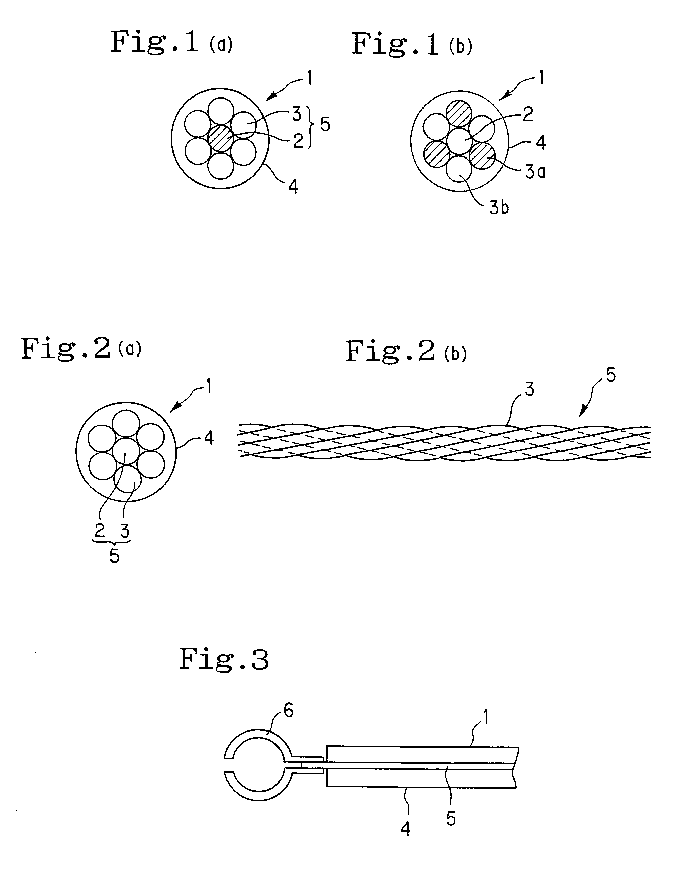
The Cr--Cu alloy does not have sufficient tensile strength and ductility and accordingly has insufficient strength; moreover, when, as shown in FIG. 3, the end of a wire conductor 1 is held by a terminal 6 or the like, in order to connect the end of the wire conductor 1 with the terminal 6 or the like, the contact between the wire conductor 1 and the terminal 6 is bad because the Cr--Cu alloy has high hardness and low flexibility.
The wire conductor whose center is composed of an alloy containing steel as a main component has a sufficient strength; however, since substantially no electricity flows in the steel portion of large resistance, no desired conductivity is obtained when the wire conductor is produced in a small diameter.

Method used


Image

  • Wire conductor for harness
  • Wire conductor for harness
  • Wire conductor for harness

Examples


example 1

There was produced a wire conductor 1 for a wiring harness shown in FIG. 1(a), comprising a core wire 2 and six strands 3 twisted around the core wire 2. As the core wire 2, a beryllium copper 25 HT wire of 0.19 mm in diameter containing 1.60% by weight of beryllium was used. As the strands 3 twisted around the core wire 2, annealed copper wires of 0.19 mm in diameter were used. As a covering material 4, a polyvinyl chloride resin was used. The pitches of twisting the strands 3 around the core wire 2 were 30 mm. Incidentally, "beryllium copper 25 HT" refers to the H material of 25 kinds of beryllium copper, which had been subjected to age hardening.

The above wire conductor 1 for a wiring harness was measured for tensile strength and conductivity according to JIS C 3002. The results are shown in Table 1.

example 2

There was produced a wire conductor 1 for a wiring harness shown in FIG. 1(b), in the same manner as in Example 1 except that half of the strands 3 twisted around the core wire 2 were composed of beryllium copper 25 HT, the remaining strands 3 and the core wire 2 were composed of annealed copper, and the strands 3a composed of beryllium copper and the strands 3b composed of annealed copper were alternately arranged around the core wire 2. The wire conductor 1 for a wiring harness was measured for tensile strength and conductivity. The results are shown in Table 1.


PUM


Abstract

A wire conductor for a wiring harness includes a stranded wire obtained by twisting strands around a core wire. The core wire is composed of beryllium copper and the strands twisted around the core wire are composed of annealed copper. Preferably, the wire conductor includes a stranded wire obtained by twisting 6, 12 or 18 strands around the core wire. Half of the strands twisted around the core wire are composed of beryllium copper, the remaining strands and the core wire are composed of annealed copper, and the strands composed of beryllium copper and the strands composed of annealed copper are alternately arranged around the core wire. The wire conductor has sufficient conductivity and strength, causes no disconnection even when produced in a small diameter, and has appropriate flexibility.

Description

BACKGROUND OF THE INVENTION AND RELATED ART STATEMENTThe present invention relates to a wire conductor for a wiring harness usable, for example, in electrical connections between electric or electronic appliances or inside such appliances, or in a wiring harness of an automobile.For example, in electrical connections between electric or electronic appliances or inside such appliances, or in a wiring harness for an automobile, there is used a wire conductor 1 for the harness, comprising (1) a stranded wire 5 obtained by twisting strands 3 around a core wire 2 and (2) an insulator cord (e.g. a polyvinyl chloride) or the like covering the stranded wire 5, such as shown in FIG. 2(a) or 2(b) [in FIG. 2(b), the insulator cord is not shown for simplicity]. As mentioned above, the wire conductor 1 for the harness is produced by twisting the strands 3 around the core wire 2; therefore, the harness has flexibility and, compared to a single strand having the same cross-sectional area used to a...

Claims


Application Information

Patent Timeline
IPC IPC(8): H01B7/00H01B5/10
CPCH01B7/0009
Inventor KAWAI, SATORU
Owner NGK INSULATORS LTD
Learn More