Modified structure for preventing electromagnetic interference of central processing unit

Inactive Publication Date: 2001-10-02
HORNG CHIN FU
View PDF8 Cites 9 Cited by
  • Summary
  • Abstract
  • Description
  • Claims
  • Application Information

AI Technical Summary

Benefits of technology

The primary object of the present invention is to provide a modified structure for preventing EMI of a CPU. The proposed modified structure comprises a base, a shielding element, two first pins, and two second pins. A CPU can be mounted in the base. Two first pin sockets are installed at one side of the base, and two second pin sockets are installed at the other side of the base. The first pins are pivotally connected to pivot joints at one side of the shielding element. The first pins are plugged in the first pin sockets of the base, and the second pins are plugged in the second pin sockets of the base. The shielding element can be closed or unfolded. When the shielding element is closed, it can cover over the CPU with lapping parts at one side thereof lapping on the second pins. The shielding element of the present invention uses the pivot joints and the lapping parts to contact with the first pins and the second pins. Moreover, the first pins and the second pins can be mounted in the motherboard. Through the contact of the first pins and the second pins with the motherboard to acquire electrically grounding finction, the shielding element can provide good electromagnetic shielding effect. Better shielding effect of EMI for the CPU can thus be achieved.
Another object of the present invention is to provide a modified structure for preventing EMI of a CPU, wherein a shielding element is pivotally connected to a base. When the base is mounted in a motherboard, first pins and second pins are also mounted in connection holes of the motherboard. The assembly of the shielding element is timesaving and laborsaving. Manpower can be greatly saved so that production cost can be effectively reduced. Moreover, because the shielding element is pivotally connected to the base, the assembly and disassembly of the CPU can be facilitated when the shielding element is unfolded. The shielding element can be dismounted when the first pins are drawn out from the first pin sockets. The disassembly of the shielding element is thus a very simple operation.

Problems solved by technology

Therefore, better shielding effect of EMI can not be achieved.
The operation is laborsome and time-consuming, resulting in inconvenience of the assembly of the shielding element 13a.
More manpower will be wasted so that production cost can not be effectively reduced.
Moreover, because the four pins 15a of the shielding element 13a have reverse hooks, it is difficult to dismount the shielding element 13a when the pins 15a are hooked in the connection holes 16a, resulting in inconvenience of the disassembly of the shielding element 13a.

Method used


Image

  • Modified structure for preventing electromagnetic interference of central processing unit
  • Modified structure for preventing electromagnetic interference of central processing unit
  • Modified structure for preventing electromagnetic interference of central processing unit

Examples


Embodiment Construction

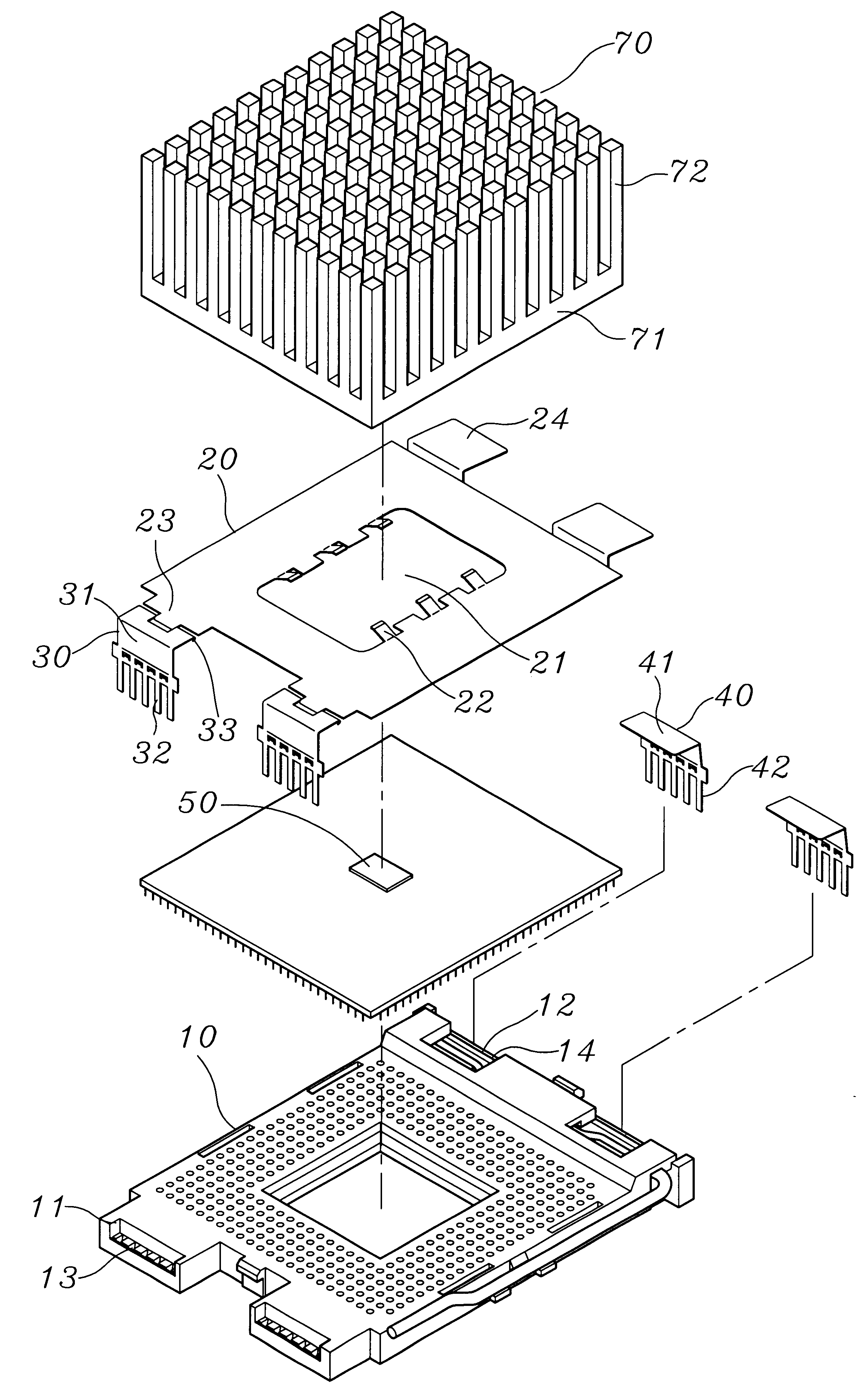
As shown in FIGS. 2 to 4, the present invention provides a modified structure for preventing EMI of a CPU. The proposed modified structure comprises a base 10, a shielding element 20, two first pins 30, and two second pins 40. The base 10 is a general zero-insertion-force (ZIF) connector, which is a well-known structure in prior art and thus will not be further described. The present invention is characterized in that two first pin sockets 11 are installed at one side of the base 10 and two second pin sockets 12 are installed at the other side of the base 10. A plurality of pin-receiving holes 13 and 14 penetrating from top to bottom are disposed on the pin sockets 11 and 12, respectively.

The shielding element 20 is made of resilient metal material. The shielding element 20 is a rectangular plate with an opening 21 at the center thereof. A plurality of resilient leaves 22 projecting upwards are installed at the edge of the opening 21. One end of each of the resilient leaf 22 forms a...


PUM


Abstract

The present invention proposes a modified structure for preventing EMI of a CPU. The proposed modified structure comprises a base, a shielding element, two first pins, and two second pins. A CPU can be mounted in the base. Two first pin sockets are installed at one side of the base, and two second pin sockets are installed at the other side of the base. Pin-receiving holes are disposed on each of the pin sockets. Pivot joints are installed at one side of the shielding element, and lapping parts are installed at the other side of the shielding element. Each first pin has a main body extending to form a plugging part. The plugging parts of the first pins are plugged in the pin-receiving holes of the first pin sockets of the base. Each second pin has a main body extending to form a plugging part. The plugging parts of the second pins are plugged in the pin-receiving holes of the second pin sockets of the base. The shielding element can be closed or unfolded. When the shielding element is closed, it can cover over the CPU with lapping parts at one side thereof lapping on the main body of the second pin. Through the contact of the first pins and the second pins with the motherboard to acquire electrically grounding function, the shielding element can provide good electromagnetic shielding effect. Better shielding effect of EMI for the CPU can thus be achieved. Moreover, the assembly of the shielding element is timesaving and laborsaving. Manpower can be greatly saved so that production cost can be effectively reduced. Additionally, the disassembly of the shielding element is a very simple operation.

Description

The present invention relates to a modified structure for preventing electromagnetic interference of a central processing unit and, more particularly, to a modified structure for preventing electromagnetic interference of a central processing unit, which not only can achieve better electromagnetic shielding effect, but also can be assembled and disassembled easily. Moreover, production cost of the proposed structure can be greatly reduced.The central processing unit (CPU) is the center of a computer. It processes data transferring from various kinds of devices, and transfers data to correct devices for executing after some judgments and calculations. Therefore, the CPU can be said to be the brain of a computer.To prevent the electromagnetic interference (EMI) from affecting the operation of a CPU, there is already a kind of structure commercially available for preventing the EMI of a CPU. As shown in FIG. 1, a CPU 10a is mounted in a base 11a. The base 11a is then mounted in a mothe...

Claims


Application Information

Patent Timeline
IPC IPC(8): H01L23/36H01L23/552H01L23/34H05K7/10H01R13/658
CPCH01L23/36H01L23/552H05K7/1069H01R13/65802H01L2924/0002H01L2924/00H01R13/6582
Inventor HORNG, CHIN FU
Owner HORNG CHIN FU
Why Eureka
Try Eureka