Mobile communication terminal device
a mobile communication and terminal technology, applied in the direction of digital transmission, transmission noise reduction, substation equipment, etc., can solve the problem of greater and achieve the effect of preventing deterioration of modulation accuracy
- Summary
- Abstract
- Description
- Claims
- Application Information
AI Technical Summary
Benefits of technology
Problems solved by technology
Method used
Image

Examples
first embodiment
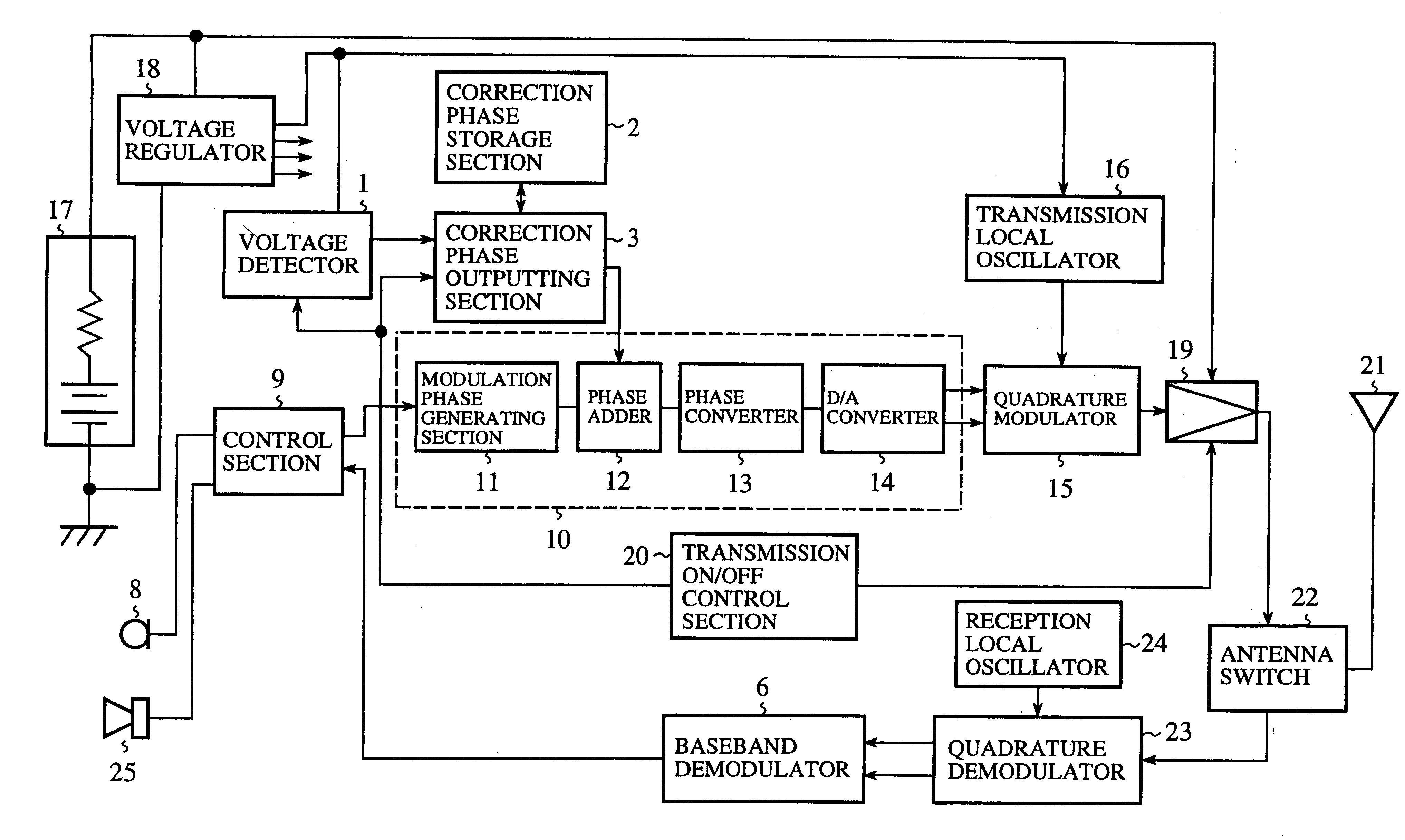
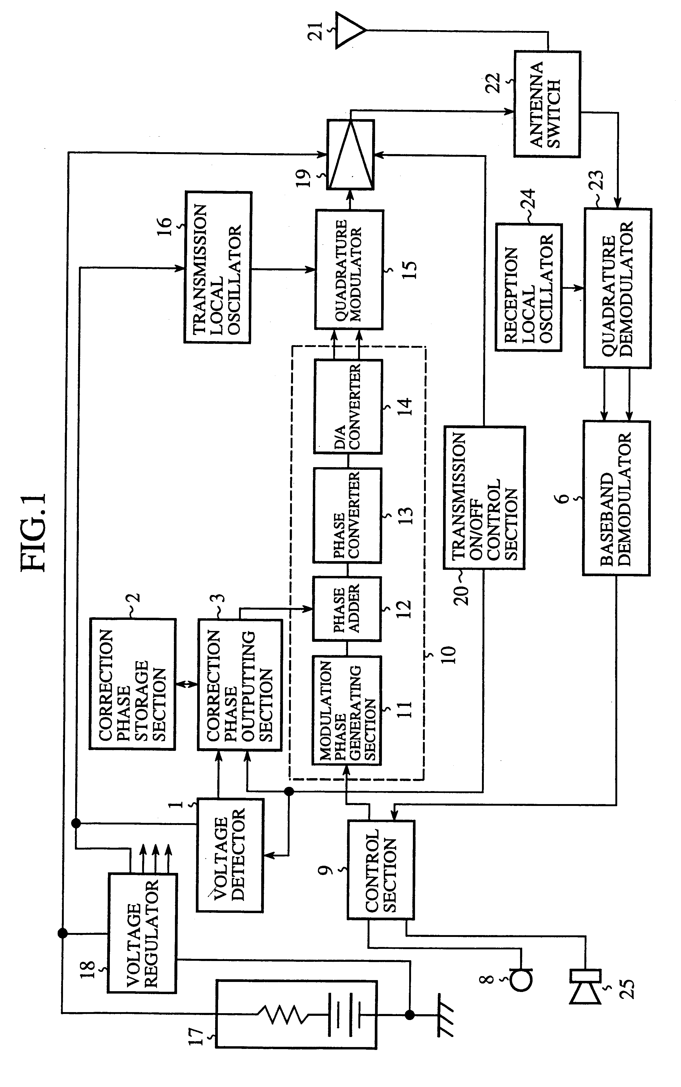
FIG. 1 is a block diagram showing a mobile communication terminal device according to a first embodiment of the present invention. Referring to FIG. 1, reference numeral 1 denotes a voltage detector for detecting the output voltage of a voltage regulator 18; 2 denotes a correction phase storage section for storing pieces of correction phase information each having a characteristic opposite to that of a phase error included in a carrier wave, the phase error being produced due to a voltage drop; and 3 denotes a correction phase outputting section for selectively outputting to a phase adder 12 correction phase information according to a battery voltage detected by the voltage detector 1 when a voltage drop occurs. It should be noted that since components in FIG. 1 which are the same as or correspond to those in FIG. 16 are denoted by like numerals, the explanation of those components will be omitted.
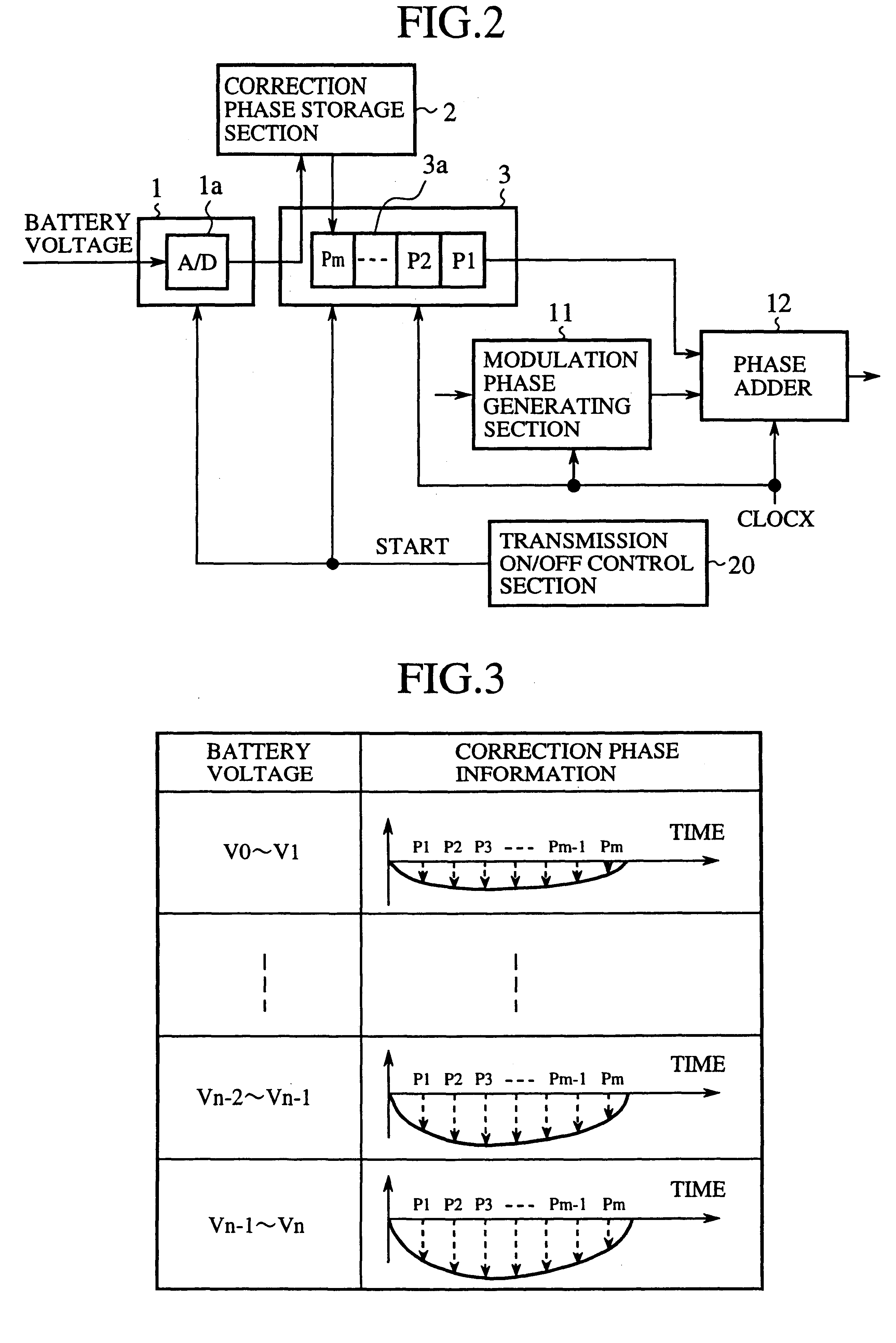
FIG. 2 is a block diagram showing a correction phase outputting section of a mobile co...
second embodiment
FIG. 7 is a block diagram showing a correction phase outputting section of a mobile communication terminal device according to a second embodiment of the present invention. Reference numeral 4 denotes a battery type identifying section for identifying a battery type to output battery type information. It should be noted that since components in FIG. 7 which are the same as or correspond to those shown in FIG. 1 are denoted by like numerals, the explanation of those components will be omitted. FIG. 8 is a diagram showing a table which stores correction phase information corresponding to both battery voltages at the time of voltage drops and battery types. This table is stored in a correction phase storage section 2. FIG. 9 is a block diagram showing the internal circuit of a nicad battery. FIG. 10 is a block diagram showing the internal circuit of a lithium ion battery.
The mobile communication terminal device according to the first embodiment selects correction phase information base...
third embodiment
FIG. 11 is a block diagram showing a correction phase outputting section of a mobile communication terminal device according to a third embodiment of the present invention. Reference numeral 9 denotes a control section for outputting the transmission power control level of a transmission power amplifier 19 to a correction phase outputting section 3. It should be noted that since components in FIG. 11 which are the same as or correspond to those shown in FIG. 1 are denoted by like numerals, the explanation of those components will be omitted. FIG. 12 is a diagram showing a table which stores correction phase information corresponding to both battery voltages at the time of voltage drops and transmission power control levels. This table is stored in a correction phase storage section 2.
The mobile communication terminal device according to the first embodiment selects correction phase information based on a battery voltage at the time of a voltage drop. However, a battery voltage drop ...
PUM
 Abstract
Description
Claims
Application Information
 - R&D
- Intellectual Property
- Life Sciences
- Materials
- Tech Scout
- Unparalleled Data Quality
- Higher Quality Content
- 60% Fewer Hallucinations
Browse by: Latest US Patents, China's latest patents, Technical Efficacy Thesaurus, Application Domain, Technology Topic, Popular Technical Reports.
© 2025 PatSnap. All rights reserved.Legal|Privacy policy|Modern Slavery Act Transparency Statement|Sitemap|About US| Contact US: help@patsnap.com