
Wall mounted heater fan with electrical outlet

a heater fan and wall mount technology, applied in the field of electric appliances, can solve the problems of consuming more wattage than can be safely provided from a single outlet, affecting the safety of the single outlet, so as to prevent overloading of the circuit and high wattage

Inactive Publication Date: 2001-08-28
TATEISHI ART K
View PDF12 Cites 13 Cited by
  • Summary
  • Abstract
  • Description
  • Claims
  • Application Information

AI Technical Summary

Benefits of technology

The appliance of the present invention is operable at different wattage settings and has a switch movable to different switch positions to determine the wattage setting of the appliance. In accordance with the present invention, the plug receptor of the appliance is blocked against plug insertion in at least one of those switch positions which would be the position in which the appliance on its own draws high wattage from the electrical outlet. This helps to prevent overloading of the circuit.

Problems solved by technology

However, there are instances where the plugging in of a single appliance may block both of those receptacles.
For instance, if the appliance has an overly large plug such as an adapter type plug, the plug itself will block both receptacles.
One serious drawback resulting from the arrangement described immediately above, is that when both of the appliances are operating together they may draw more wattage than can be safely provided from the single outlet.
Typically, an electrical wall outlet operates at a maximum of 1500 watts and if the two appliances together require more than 1500 watts, this results in an overloading of the circuit.
For this reason, the inclusion of a separate plug has not been allowed to date, for an electrical heater fan having a maximum output at 1500 watts.

Method used


Image

  • Wall mounted heater fan with electrical outlet
  • Wall mounted heater fan with electrical outlet
  • Wall mounted heater fan with electrical outlet

Examples


Embodiment Construction

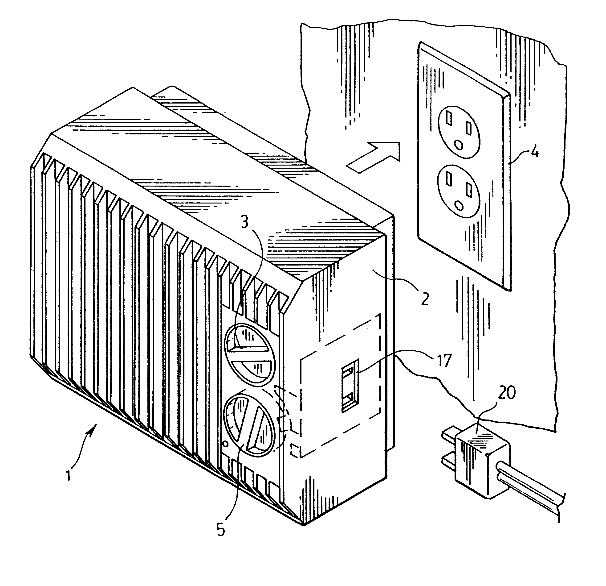
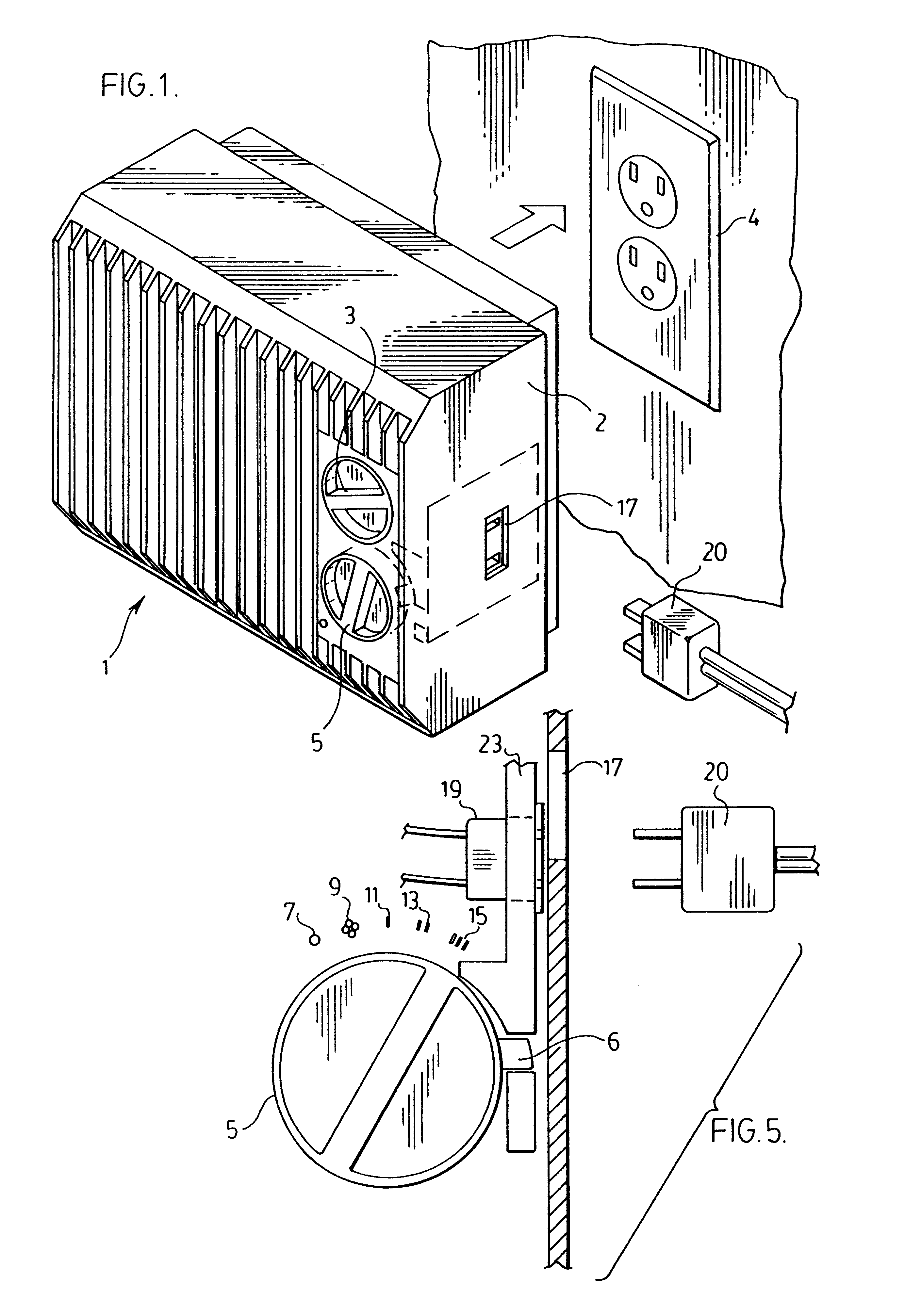
FIG. 1 shows an electrical heater fan generally indicated at 1 which plugs into an electrical wall outlet 4. The heater fan which mounts directly to the wall by an electrical plug (not shown) at the back of the heater fan. The main casing 2 of the heater fan blocks the unused receptacle in the wall outlet.

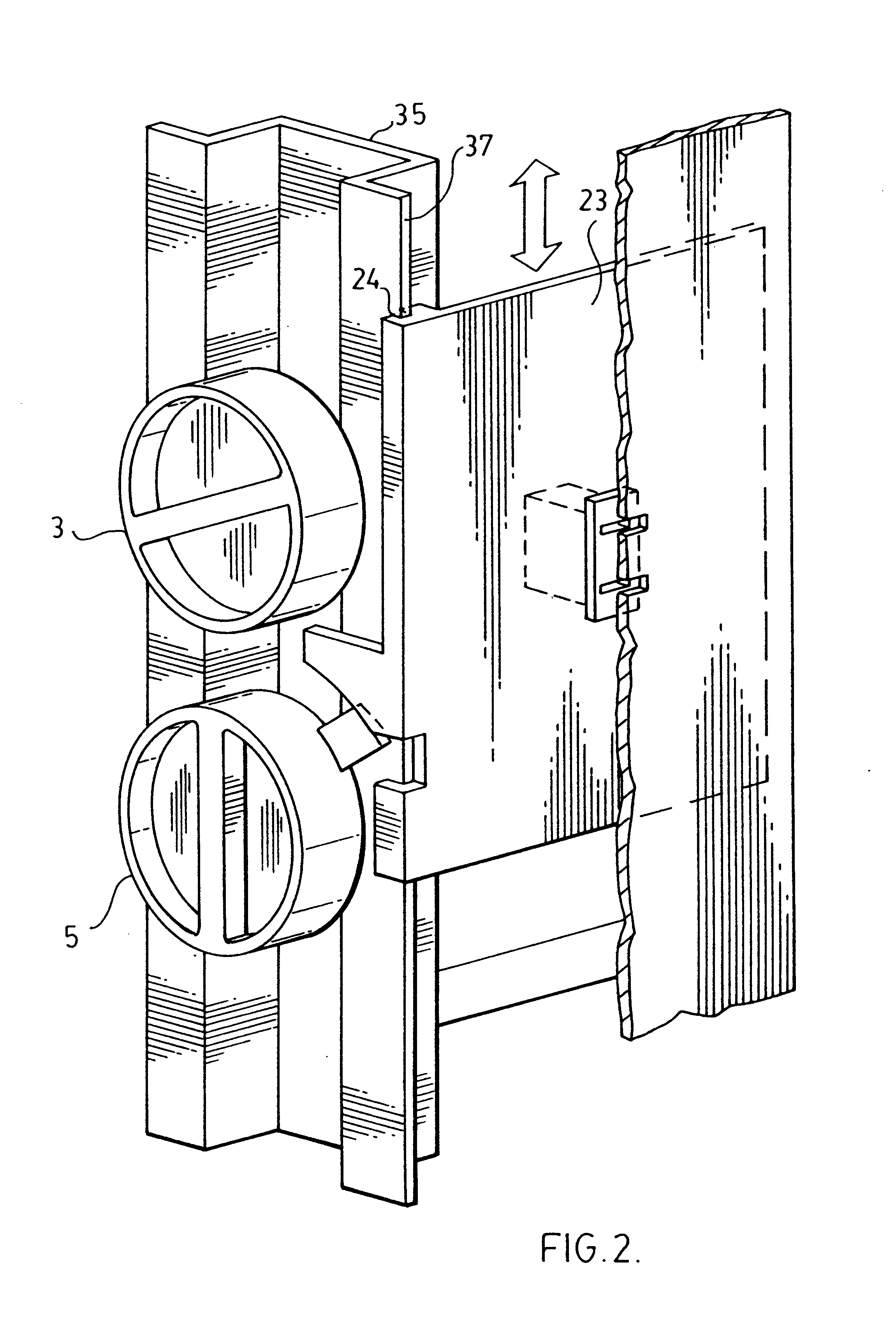
The heater fan has first and second rotating controls 3 and 5 respectively. Control 3 sets the operating temperature for the heater fan when it is used in a heater mode and control 5 is a rotating switch movable to a number of different switch positions as shown in FIGS. 2 and 4 of the drawings. These positions comprise an off position 7, a fan position 9 where the unit operates strictly as a fan without any heater activity and first, second and third heater positions 11, 13 and 15 respectively. The operating wattages for these three heater switch positions are 500 watts in switch position 11, 1000 watts in switch position 13 and 1500 watts in switch position 15. The 1500 watt sett...


PUM


Abstract

An electrical appliance has a plug receptor to receive the plug of another appliance such that both appliances can draw power from a single electrical outlet. The appliance of the present invention is operable at different wattages and has a switch which is movable to different switch settings to determine the wattage at which the appliance is operating. When the switch is set such that the appliance operates at a high wattage, the plug receptor is blocked from access to the plug of the other appliance to prevent over loading of the electrical outlet.

Description

The present invention relates to an electrical appliance with its own plug receptor for receiving the plug of another electrical appliance. Through the provision of the plug receptor, both appliances draw power through a common electrical outlet.A typical electrical wall outlet is one which has receptacles for the plugs for two separate electrical appliances. However, there are instances where the plugging in of a single appliance may block both of those receptacles. For instance, if the appliance has an overly large plug such as an adapter type plug, the plug itself will block both receptacles. In other instances, the plug may be mounted directly to the back of an appliance such as a wall mounted heater fan where the body of the fan blocks the other receptacle.In the above example, it is possible to put a totally separate plug receptacle into the actual body of the first appliance plugged into the wall outlet. A second appliance can then be plugged into the first appliance whereby ...

Claims


Application Information

Patent Timeline
Patent Type & Authority Patents(United States)
IPC IPC(8): H01R13/44H01R13/453
CPCH01R13/4534Y10S439/911
Inventor TATEISHI, ART K.
Owner TATEISHI ART K
Learn More