Automatic transmission

a transmission and automatic technology, applied in mechanical equipment, gearing details, gearing, etc., can solve the problems of fatigue to lose endurance, increase the cost of automatic transmission,

Inactive Publication Date: 2001-08-21
SUBARU CORP
View PDF5 Cites 5 Cited by
  • Summary
  • Abstract
  • Description
  • Claims
  • Application Information

AI Technical Summary

Problems solved by technology

When the vehicle makes a sudden start, since this load becomes very large, the driven plate 76 is fatigued to lose endurance.
On the other hand, in order to enhance the endurance or strength of the friction plates, the use of a material of high grade provides the automatic transmission with an increase in cost.

Method used


Image

  • Automatic transmission
  • Automatic transmission
  • Automatic transmission

Examples


Embodiment Construction

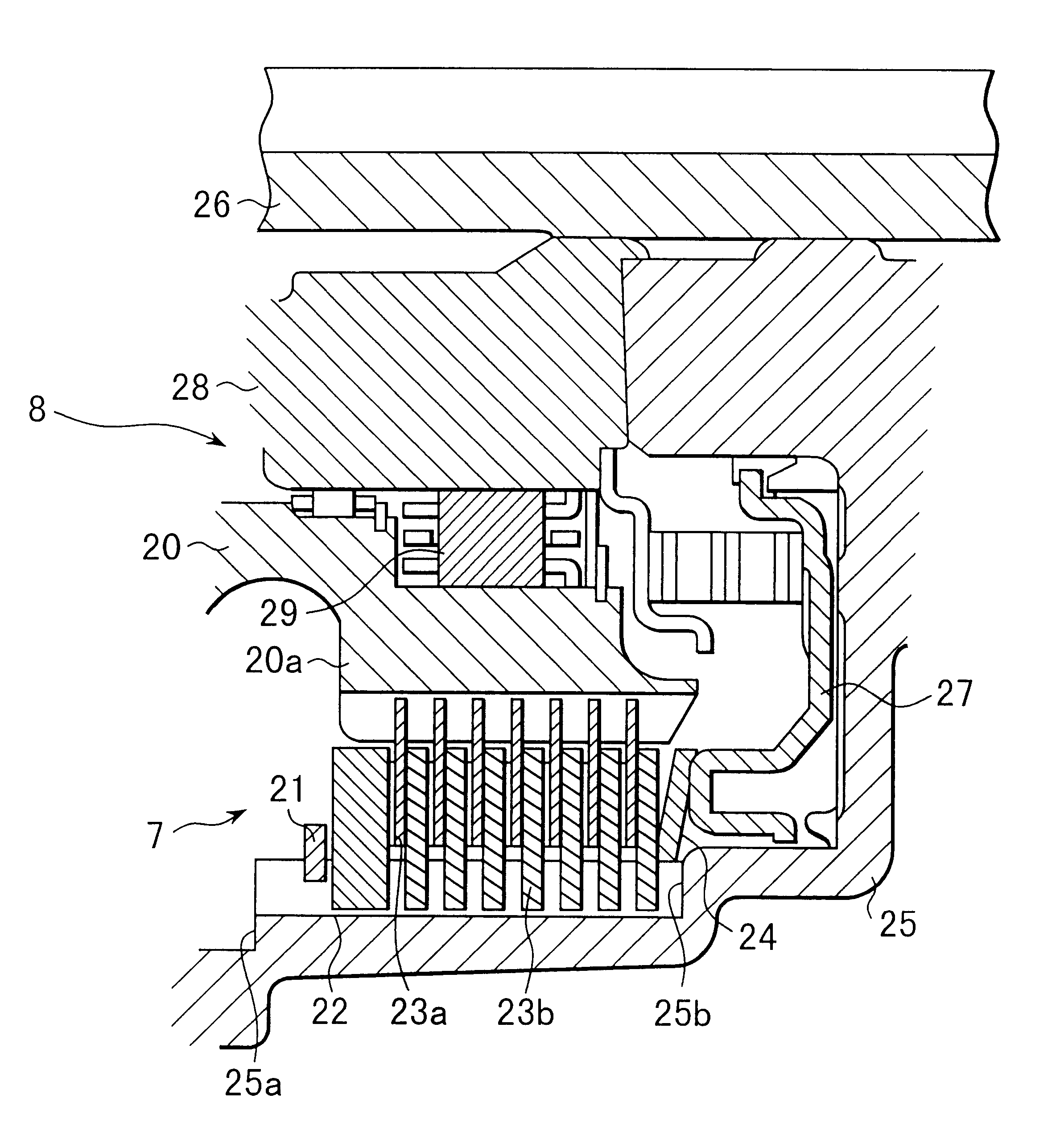
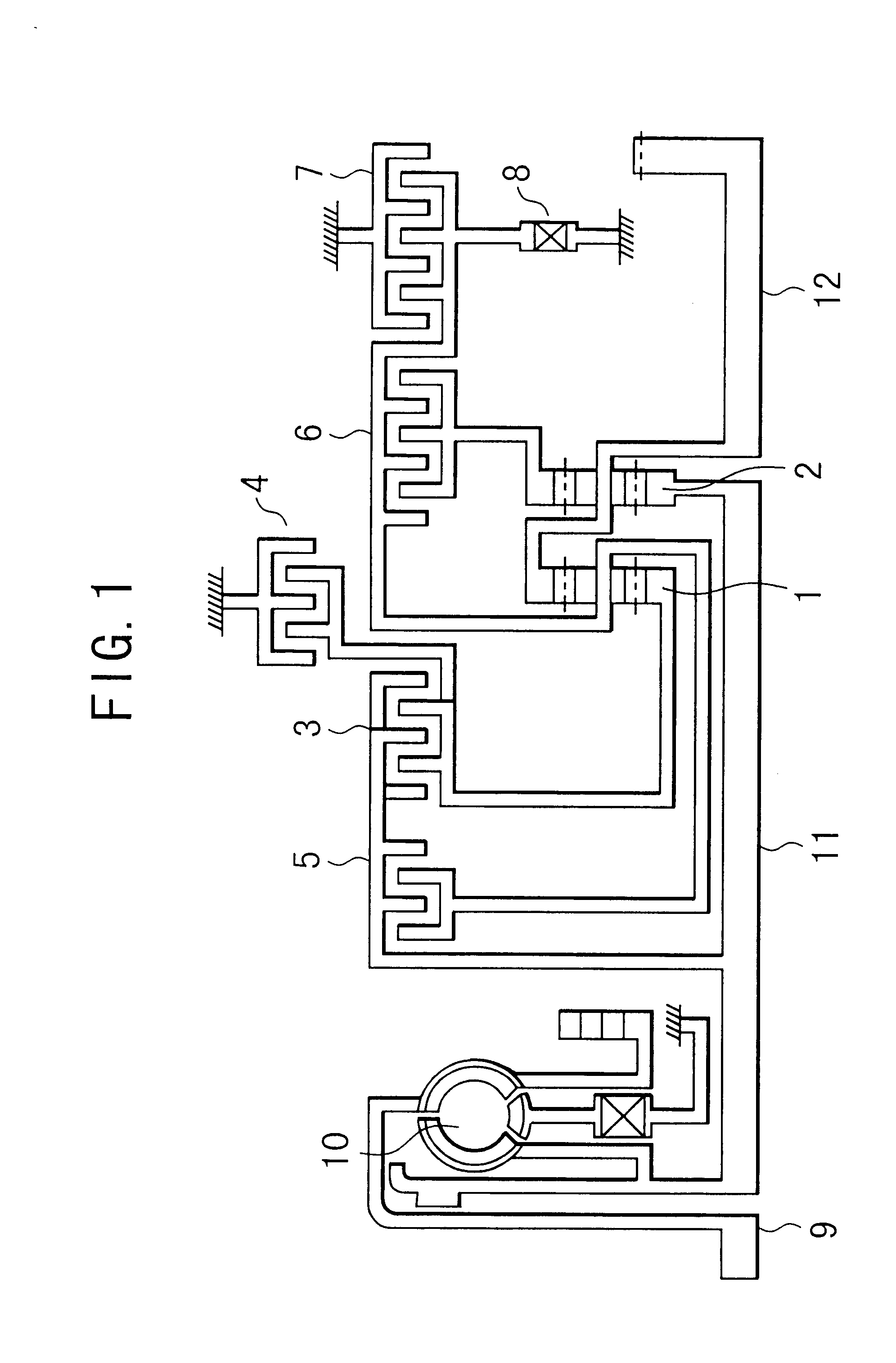
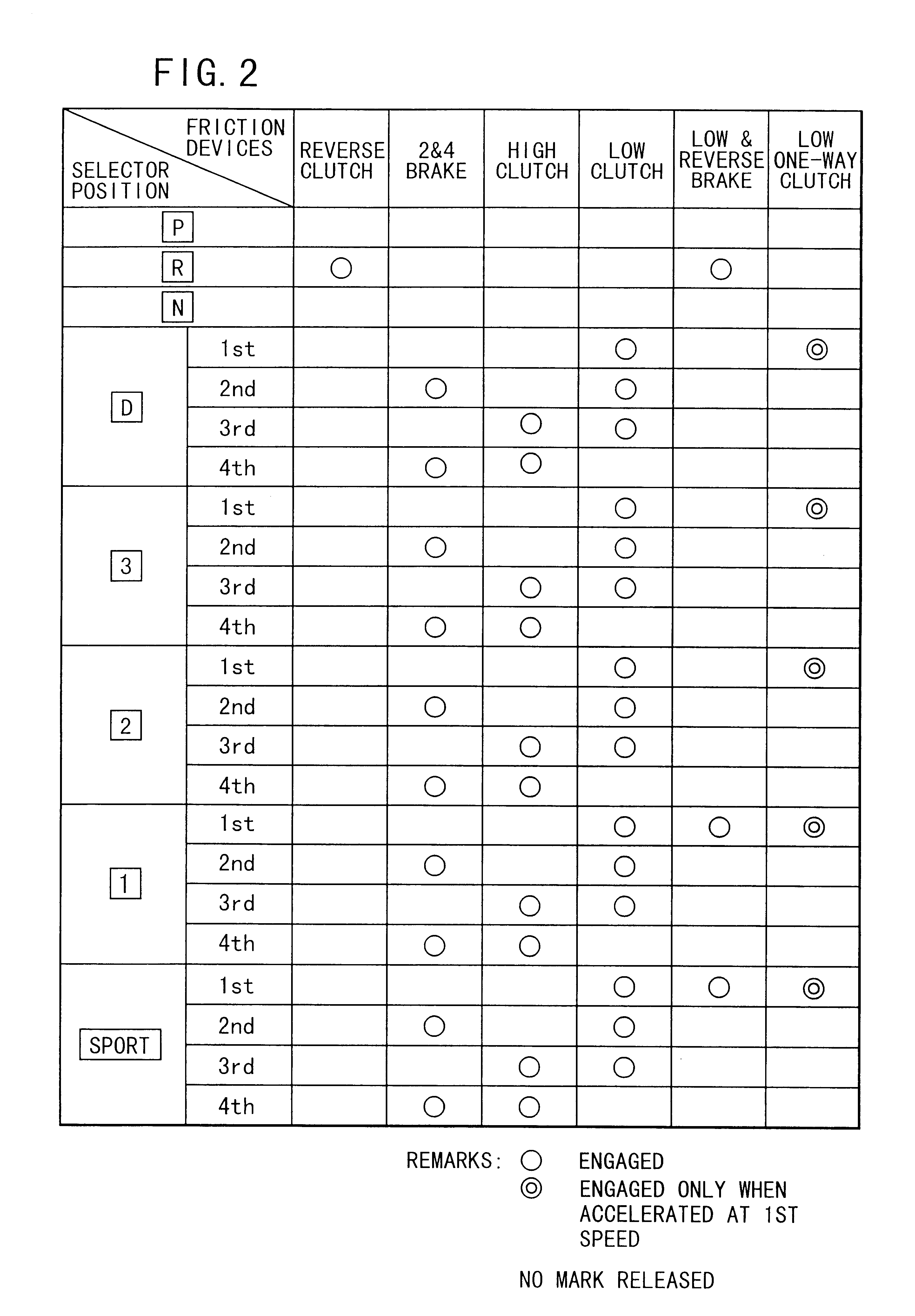
FIG. 1 is a schematic diagram showing an arrangement of gears, a torque converter, clutches and brakes for an automatic transmission. In the drawing, driving force of a crank shaft 9 of an engine is transmitted to a turbine shaft 11 through s torque converter 10. The turbine shaft 11 which is an input shaft of the automatic transmission is drivingly connected to a sun gear of a rear planetary gear set 2. On the other hand, a reduction drive shaft 12 which is an output shaft of the transmission is drivingly connected to a ring gear of a front planetary gear set 1 and a planetary carrier of the rear planetary gear set 2. Respective members, namely sun gears, pinions, ring gears and planetary carriers, of the front and rear planetary gear sets 1, 2 are drivingly connected to three multiple-disk clutches (reverse clutch 3, high clutch 5 and low clutch 6), two multiple-disk brakes (2 & 4 brake 4 and low & reverse brake 7) and a low one-way clutch 8. These friction elements (clutches and ...


PUM


Abstract

An automatic transmission comprises a friction engaging means having a plurality of first plates spline-fitted to a hub and a plurality of second plates spline-fitted to a drum and disposed in an interleaving relation to the first plates, an one-way clutch provided in the hub and having a plurality of sprags for locking the rotation of the hub when the hub rotates in a locking direction and a control means for temporarily releasing the friction engaging means for a specified timespan when the friction engaging means is in an engagement condition and when the hub rotates in a locking direction.

Description

1. Field of the InventionThe present invention relates to an automatic transmission, and more particularly, to an engagement control for a friction device of an automatic transmission.2. Background ArtAn automatic transmission for a motor vehicle has a planetary gear set constituted of sun gears, ring gears, pinions and the like. The speed change of the transmission is accomplished by engaging or releasing friction devices such as multiple-disc clutches or multiple-disc brakes. Generally, the friction devices comprise a plurality of drive plates connected to an input side and a plurality of driven plates connected to an output side disposed in an interleaving relation to the drive plates. When a pressure of a pressure plate is applied to those drive and driven plates, power is transmitted from the drive plates to the driven plates through a frictional contact therebetween.Besides these multiple-disk type friction elements, a one-way clutch is used for engaging or releasing gears in ...

Claims


Application Information

Patent Timeline
Patent Type & Authority Patents(United States)
IPC IPC(8): F16H57/00F16H57/08F16H63/30F16H61/08
CPCF16H57/08F16H63/3026Y10T477/6937
Inventor SATO, KEIJINAKAYAMA, JUNSUZUKI, NAOTOFUJISAWA, TADAOSAWAOKA, MASATO
Owner SUBARU CORP
Why Eureka
Try Eureka