
Indicator lights for motor vehicles

a technology for indicator lights and motor vehicles, applied in the field of indicator lights, can solve the problem of not being very original in the outward appearance of such a known type of indicator lights, and achieve the effect of a new visual appearan

Inactive Publication Date: 2001-08-14
VALEO VISION SA
View PDF4 Cites 19 Cited by
  • Summary
  • Abstract
  • Description
  • Claims
  • Application Information

AI Technical Summary

Benefits of technology

An object of the present invention is to provide an indicator light of the type mentioned above, which, while satisfying the photometric regulations and being, where appropriate, without any light flux recuperator, has a novel visual appearance both when extinguished and when lit, which hardly varies when the observer moves around the vehicle.

Problems solved by technology

The outward aesthetic appearance of such a known type of indicator light is not very original.
This sparkling appearance, which does give the indicator light some novelty from the aesthetic point of view, has the disadvantage that it has an appearance, both when extinguished and when lit, which varies in a very marked manner when the observer moves around the vehicle.

Method used


Image

  • Indicator lights for motor vehicles
  • Indicator lights for motor vehicles
  • Indicator lights for motor vehicles

Examples


Embodiment Construction

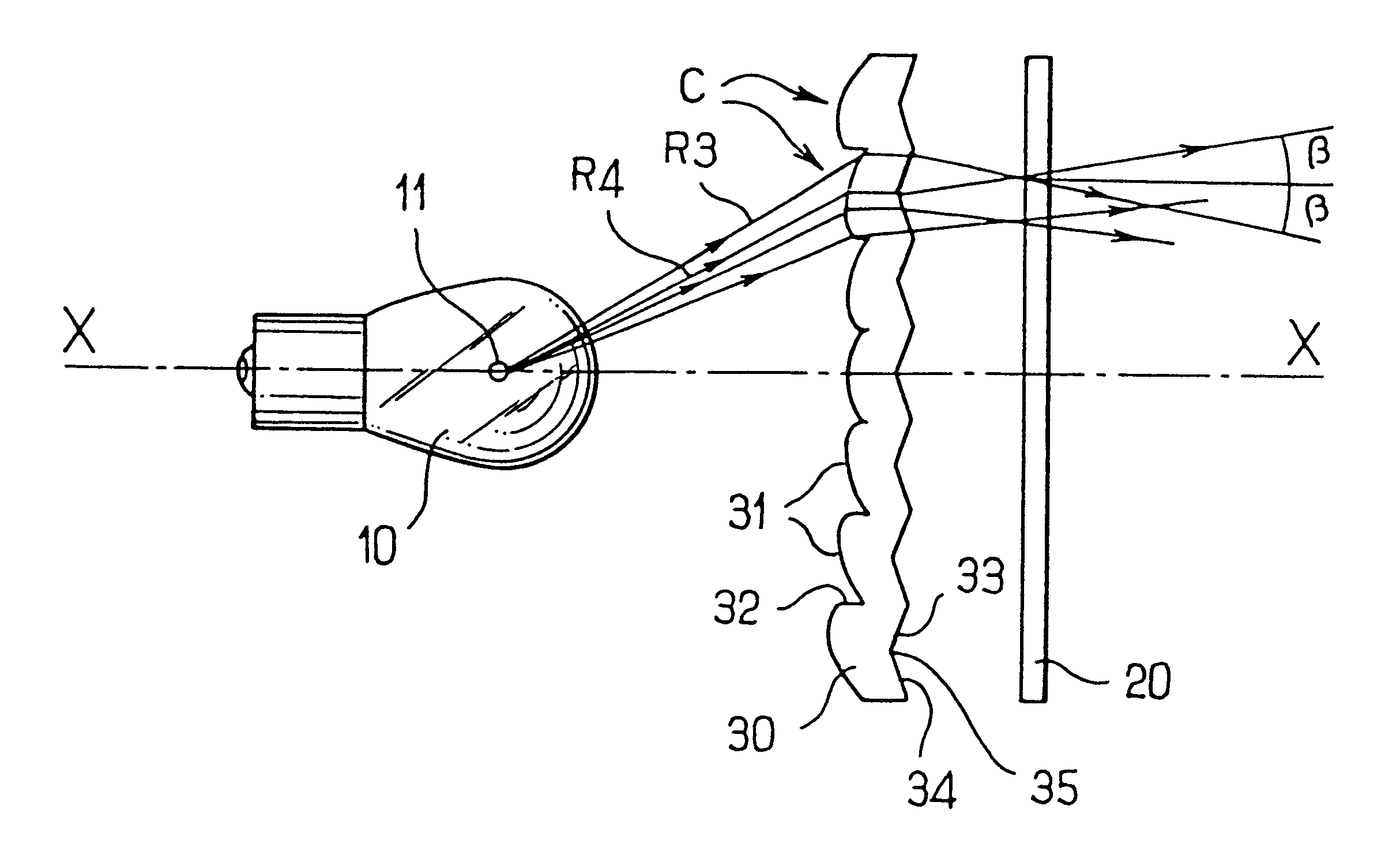
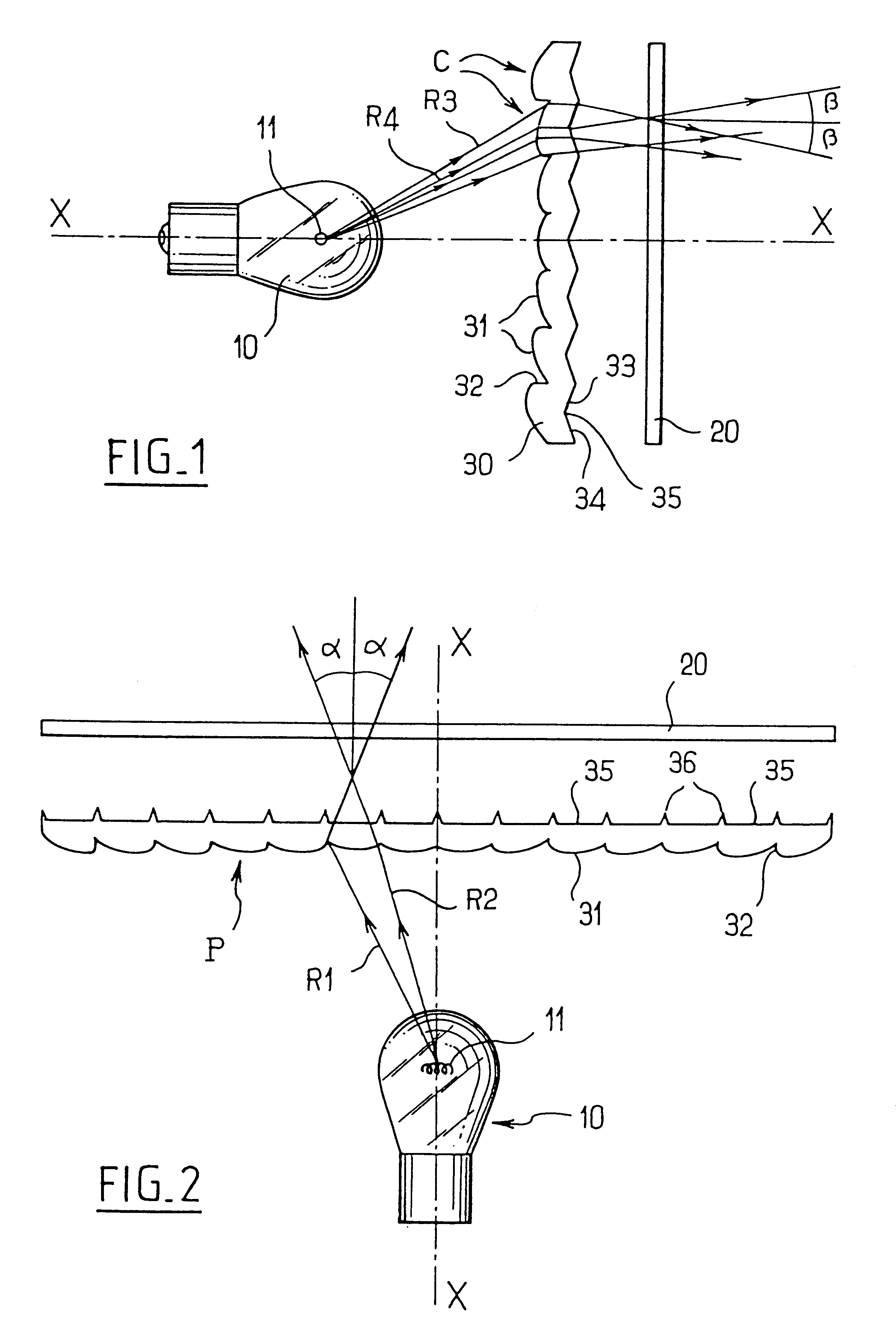
With reference first to FIGS. 1 and 2, there is shown an indicator light which comprises: a light source 10, which is typically a filament lamp 11; an intermediate screen 30; and a cover glass or lens 20, which is preferably smooth on both of its faces, whether or not such faces are parallel to the intermediate screen 30. In the present example, the intermediate screen 30 and the cover lens 20 lie in planes which are essentially at right angles to the general direction X--X of emission of light by the indicator light, which is defined in the present example by the axis of the lamp 10. It will, however, be clearly understood that, although the screen 30 and cover glass 20 presented here are generally planar, curved profiles may also be envisaged.

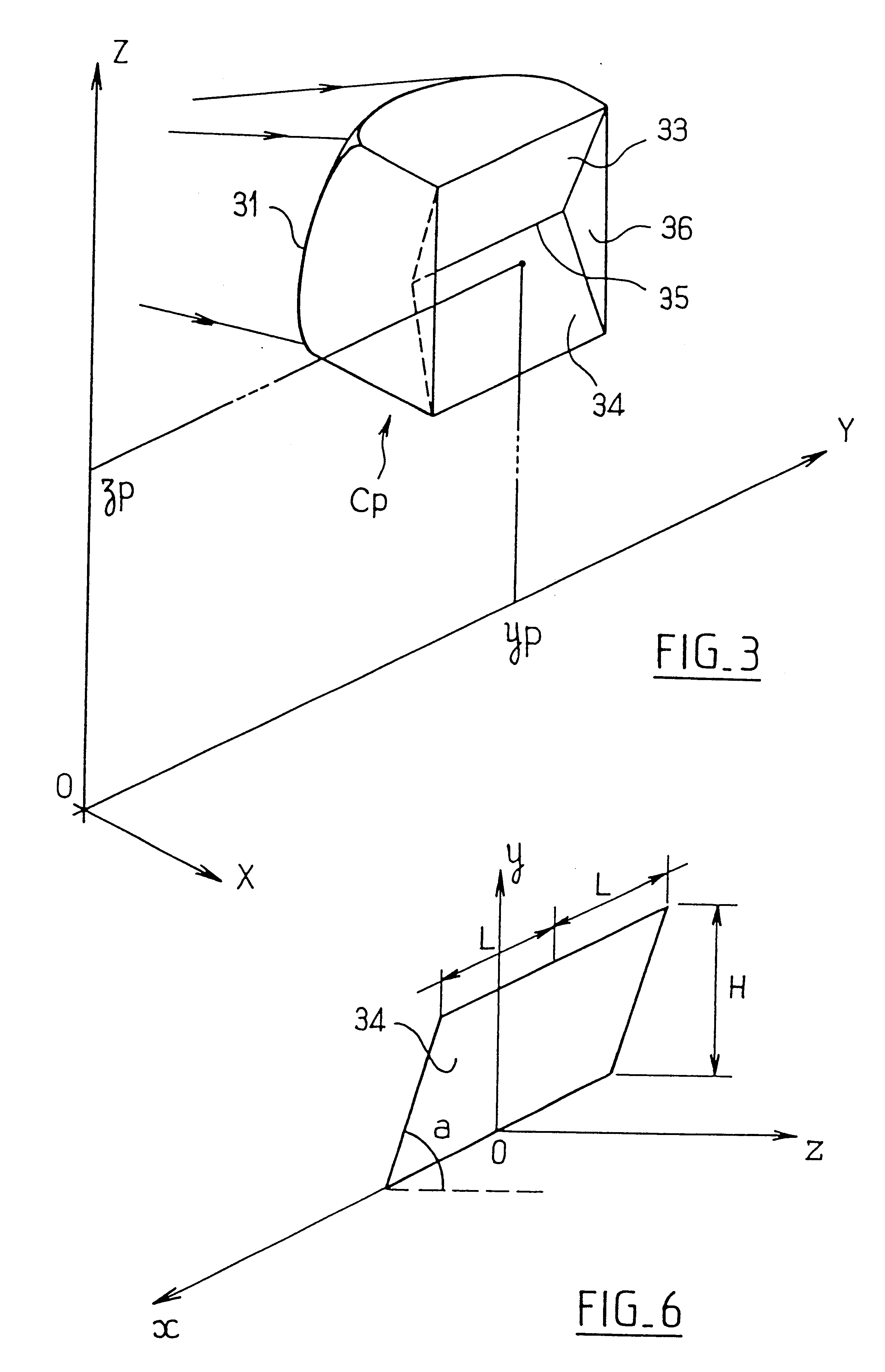
The intermediate screen 30, in this example, includes on its internal face a plurality of generally convex surfaces 31 which are defined within rectangular contours, such contours being squares and defining individual optical cells.

As will be...


PUM


Abstract

An indicator light for a motor vehicle has a point source, an intermediate screen which receives the light directly from the source, and a cover glass outside the screen. The intermediate screen comprises a series of optical cells, each of which has, on an internal face, a curved surface for straightening and spreading the light. Each cell further has, on an outer face, a set of at least two flat facets which are oblique with respect to a plane of the intermediate screen.

Description

The present invention relates to indicator lights, or indicating lights, for motor vehicles, and more particularly to indicator lights which include a light source which is substantially a point source, an intermediate screen, and a cover glass, or lens, in front of the screen, the intermediate screen and the cover lens both being interposed in the path of an essentially parallel beam emitted by the indicator light.Such an indicator light is known in general terms, in which the intermediate screen, and sometimes the cover lens, include optical arrangements for giving the indicator light the desired photometry and, optionally, a particular styling appearance.A first conventional approach consists of giving the intermediate screen a Fresnel lens which is focused on the light source, so as to restitute, at the exit of the indicator light, an essentially parallel beam. In that case, the cover lens is formed with billet-shaped or toroidal elements for diffusion of the light both horizont...

Claims


Application Information

Patent Timeline
Patent Type & Authority Patents(United States)
IPC IPC(8): F21V9/08F21V5/00F21V9/00F21S8/10
CPCF21S48/2218F21S48/2212F21S43/26F21S43/255
Inventor ALBOU, PIERRE
Owner VALEO VISION SA
Learn More