
Assembly containing a wheel and a suspension integrated with the wheel

a technology of suspension and wheel, which is applied in the direction of rigid suspension, vehicle springs, transportation and packaging, etc., can solve the problems of cumbersome the height dimension is not good, and the installation of suspension on the vehicle is even more cumbersom

Inactive Publication Date: 2001-07-10
CONCEPTION & DEV MICHELIN SA
View PDF11 Cites 58 Cited by
  • Summary
  • Abstract
  • Description
  • Claims
  • Application Information

AI Technical Summary

Benefits of technology

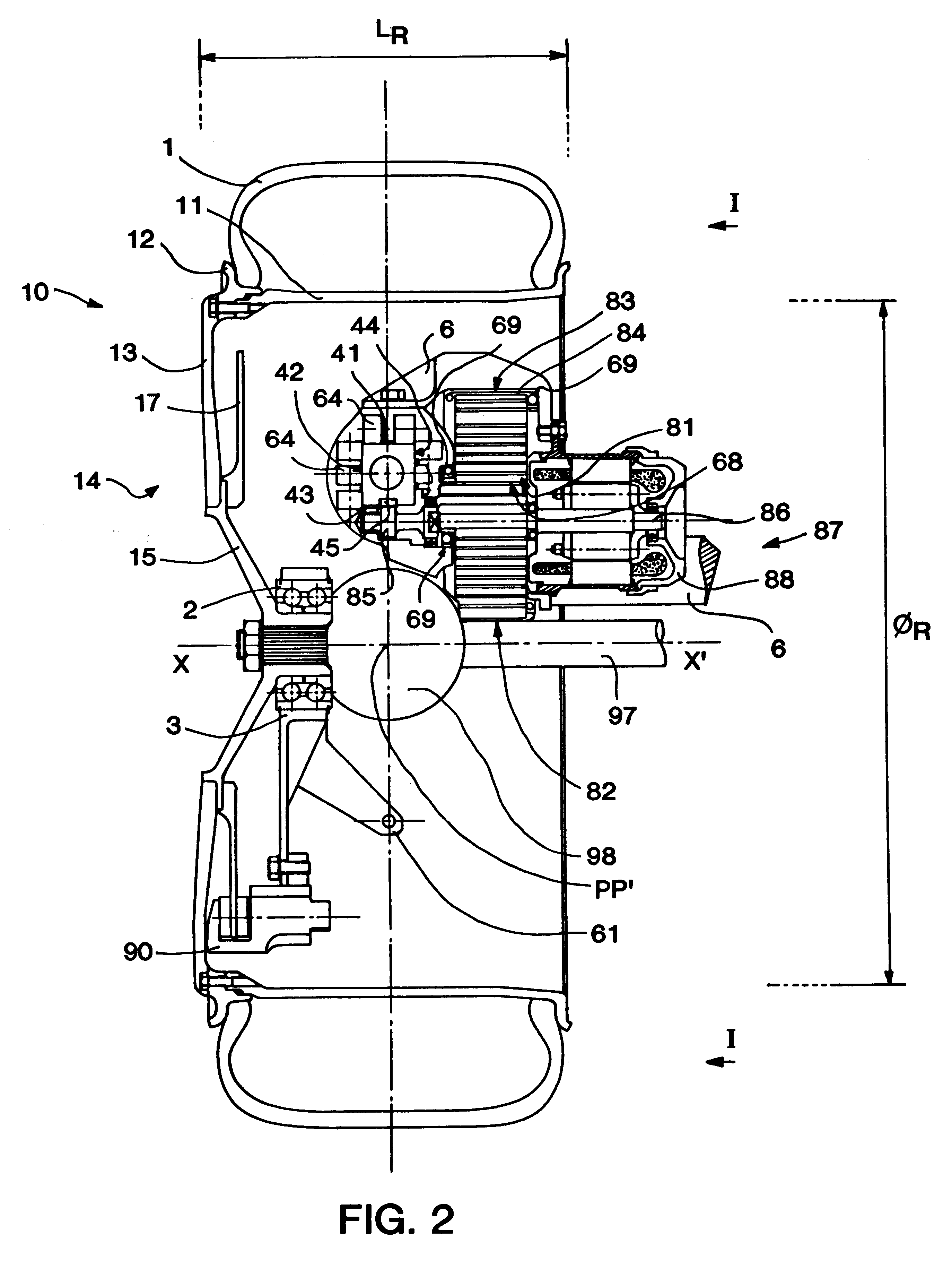
The invention thus proposes an assembly making it possible, in a preferred embodiment, to integrate the guidance necessary for wheel deflection and the elements making it possible to ensure the necessary flexibility and control of deflection inside the wheel. In that way, it is possible for the essential functions of the suspension (guidance of the wheel plane, degree of freedom in the desired direction and control of deflection movements) to be integrated in the actual interior space of the wheel. It is thus possible very simply to mount that assembly to the chassis of the vehicle in any suitable manner and, notably, rigidly. In the latter case, the guide member plays a support role for suspension and is integrated with the chassis, which makes very simple use possible. The support being intended to be locked in vertical deflection relative to the chassis and the guide member being mounted locked in vertical deflection relative to the support, the guide member is therefore locked in vertical deflection relative to the chassis.
The electronic automatic control means available at the present time make it possible to run an electric motor more rapidly and more directly than a hydraulic or pneumatic component. That is why, in a particularly advantageous variant, the invention proposes using a linear or rotary electric motor for controlling the deflection movements of the wheel. An arrangement is thus proposed which makes it possible to house such a motor in the assembly according to the invention, while remaining roughly within the interior space limits of the wheel. The invention thus has the advantage of lending itself particularly well to active control of the suspension characteristics and, more specifically, to direct electric control of the suspension characteristics.
Let us note that, when translation guidance of the bar is "friction-free," that is, involving as little friction as possible, control of the deflection movement is thereby facilitated, for it is not distorted by parasite frictions, the extent of which is often variable. Roller guidance is very appropriate. Rollers cooperating with roller ways provided on the bar can be used, the rollers being mounted rotating on the guide member. Relative sliding contact surfaces could thus be imagined, insofar as they involve appropriate treatment or insofar as they are sufficiently lubricated. For example, a fluid bearing can be used. That variant lends itself particularly well to control of deflection essentially by means of an electromechanical machine that can be run for that purpose, for the absence of boundary friction simplifies its operation and improves overall performances.

Problems solved by technology

All of the suspensions used at the present time on vehicles have the common characteristic of being rather cumbersome.
Even the MacPherson strut, the growing use of which is known to be due to the greater space it leaves for installing a motor power unit in transverse position, introduces some problems, including its height dimension.
In general, that leads to making installation of the suspension on the vehicle even more cumbersome, by increasing the space occupied by springs and / or shock absorbers, not to mention adding extra elements forming the spring or shock absorber.

Method used


Image

  • Assembly containing a wheel and a suspension integrated with the wheel
  • Assembly containing a wheel and a suspension integrated with the wheel
  • Assembly containing a wheel and a suspension integrated with the wheel

Examples


Embodiment Construction

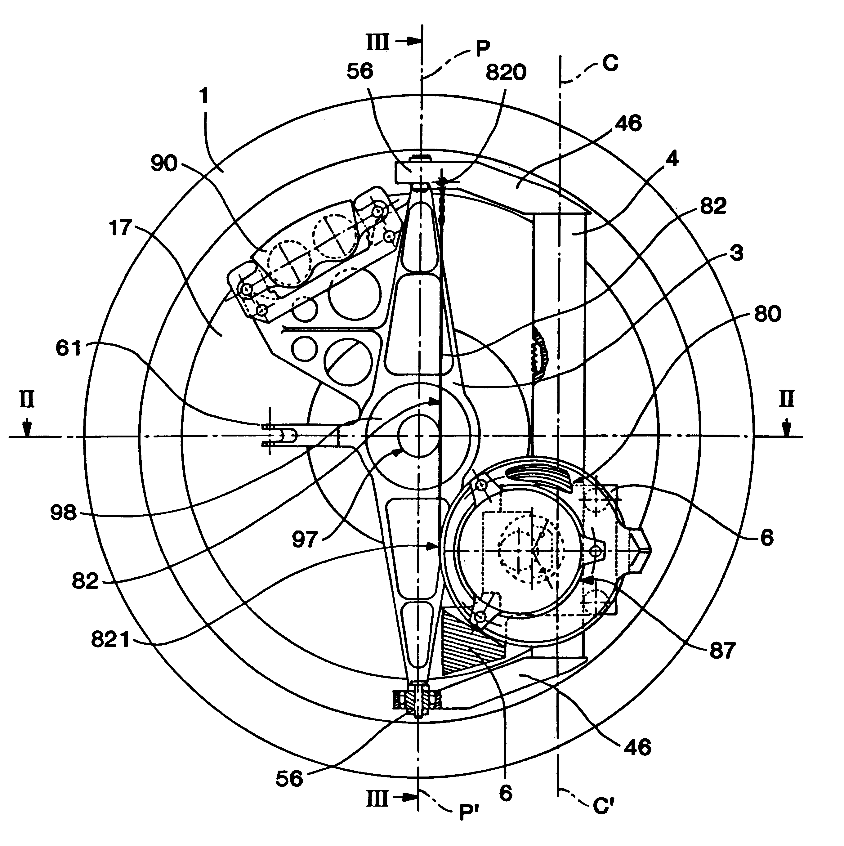
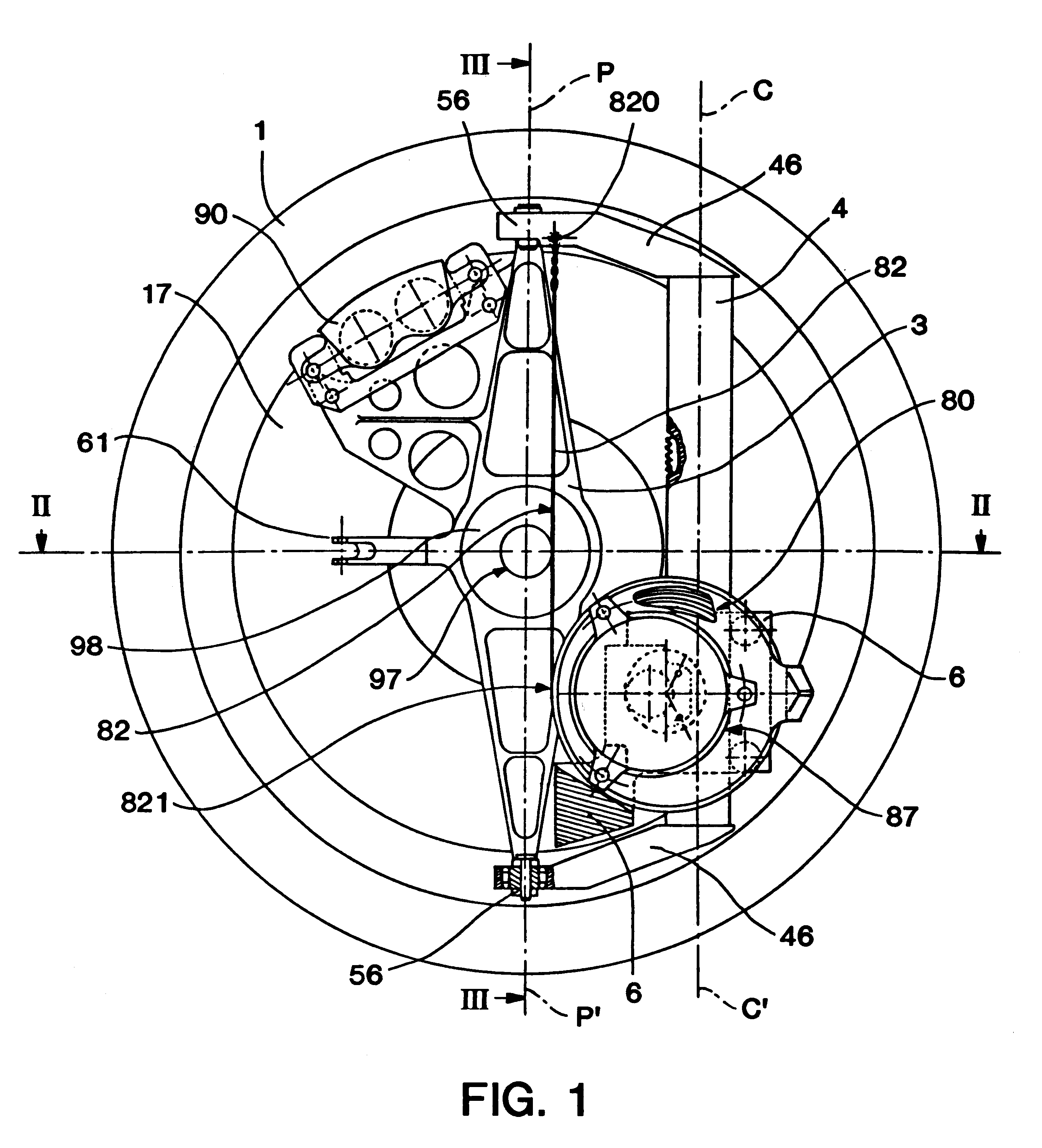
In the different figures a tire 1 can be seen, mounted on a rim 10, the latter being made in two parts 11 and 12, axially separable, following one of the possible methods of mounting a tire 1 on a rim. Other solutions could, of course, be adopted, such as a tire permanently mounted on its rim, or a noninflated or nonpneumatic tire, the invention not concerning the means ensuring contact with the road.

The rim 10 is connected to a wheel disk 13. The rim 10 and the disk 13 form a wheel 14. Said wheel 14 is mounted on a hub 15 by two studs (not represented). A brake disk 17 is integral with the hub 15. The working details of mounting of a wheel and a brake disk on a hub are well known and do not require fuller explanation. The subassembly just described constitutes the rotating parts of the assembly according to the invention. Their axis of rotation is axis XX'. These rotating parts are mounted on a wheel carrier 3 by means of a bearing 2.

The wheel carrier 3 is in turn rendered integral...


PUM


Abstract

A suspension assembly of a motor vehicle which assemble includes a wheel carrier and a guide member to guide the wheel carrier in relative translation. The wheel carrier is mounted on the guide member by means of a bar sliding in the guide member guided by rollers turning on roller ways arranged on the bar. The assembly includes a spiral spring acting between the bar of the wheel carrier and a guide member of an electromechanical machine that is operated to control the suspension deflection movements.

Description

BACKGROUND OF INVENTIONThe present invention concerns the suspension of vehicles and, more specifically, the guidance of a vehicle wheel in relation to the chassis of that vehicle, as well as control of deflection of the wheel in relation to the chassis.It is known that a wheel is mounted on a hub, and that the hub is mounted on a wheel carrier by means of a bearing defining the axis of rotation of the wheel. Guidance of the wheel consists of making possible a displacement of the wheel carrier in relation to the vehicle to an extent sufficient for the suspension of the vehicle. At the same time, guidance of the wheel should be such that control of the path of the vehicle is ensured with the utmost care. The deflection movement sought is very wide vertically. It may be desired to permit a slight movement longitudinally, while ideally it is sought to prevent any relative transverse movement. Furthermore, the steering and camber variations that might induce all these movements have to ...

Claims


Application Information

Patent Timeline
Patent Type & Authority Patents(United States)
IPC IPC(8): B60G17/015B60G3/00B60G3/01B60G11/14B60G13/14B60G17/00
CPCB60G3/01B60G17/0157B60G2202/12B60G2202/42B60G2500/30B60G2204/149B60G2204/4232B60G2204/62B60G2204/148
Inventor LAURENT, DANIELWALSER, DANIEL
Owner CONCEPTION & DEV MICHELIN SA
Learn More