
In-situ method to remove iron and other metals from solution in groundwater down gradient from permeable reactive barrier

a reactive barrier and groundwater technology, applied in water/sludge/sewage treatment, contaminated soil reclamation, chemistry apparatus and processes, etc., can solve the problems of adding other manmade contaminants to the groundwater, contaminating the groundwater in many localities, and natural and manmade impurities

Inactive Publication Date: 2001-07-03
THE UNITED STATES AS REPRESENTED BY THE DEPARTMENT OF ENERGY
View PDF7 Cites 17 Cited by
  • Summary
  • Abstract
  • Description
  • Claims
  • Application Information

AI Technical Summary

Benefits of technology

, which will become apparent from the following description, have been achieved by a novel improvement to in-situ groundwater treatment systems to remove secondary sources of groundwater contamination released by the treatment media from primary in-situ treatment systems into native aquifers. The primary in-situ treatment system, for use with the treatment system of this invention, relies on the flow of groundwater, through an aquifer, into the primary treatment system to decontaminate the groundwater through the use of a metallic treatment material. The primary treatment system may add metallic-based contaminants while decontaminating the groundwater. The improvement of this invention is to oxygenate the oxygen-deficient groundwater after in-situ treatment by the metallic treatment material in order to remove the metallic-based contaminants added to groundwater by the primary in-situ treatment system. The treatment system of this invention is particularly useful when the groundwater is maintained in an anaerobic condition, and the primary treatment system and media is maintained under anaerobic conditions.

Problems solved by technology

Groundwater in many localities has become contaminated by both natural and manmade impurities.
These in-situ treatment systems, while removing or neutralizing many dangerous contaminants, may add other manmade contaminants to the groundwater.
The primary treatment system may add metallic-based contaminants while decontaminating the groundwater.

Method used


Image

  • In-situ method to remove iron and other metals from solution in groundwater down gradient from permeable reactive barrier
  • In-situ method to remove iron and other metals from solution in groundwater down gradient from permeable reactive barrier
  • In-situ method to remove iron and other metals from solution in groundwater down gradient from permeable reactive barrier

Examples


Embodiment Construction

(s)

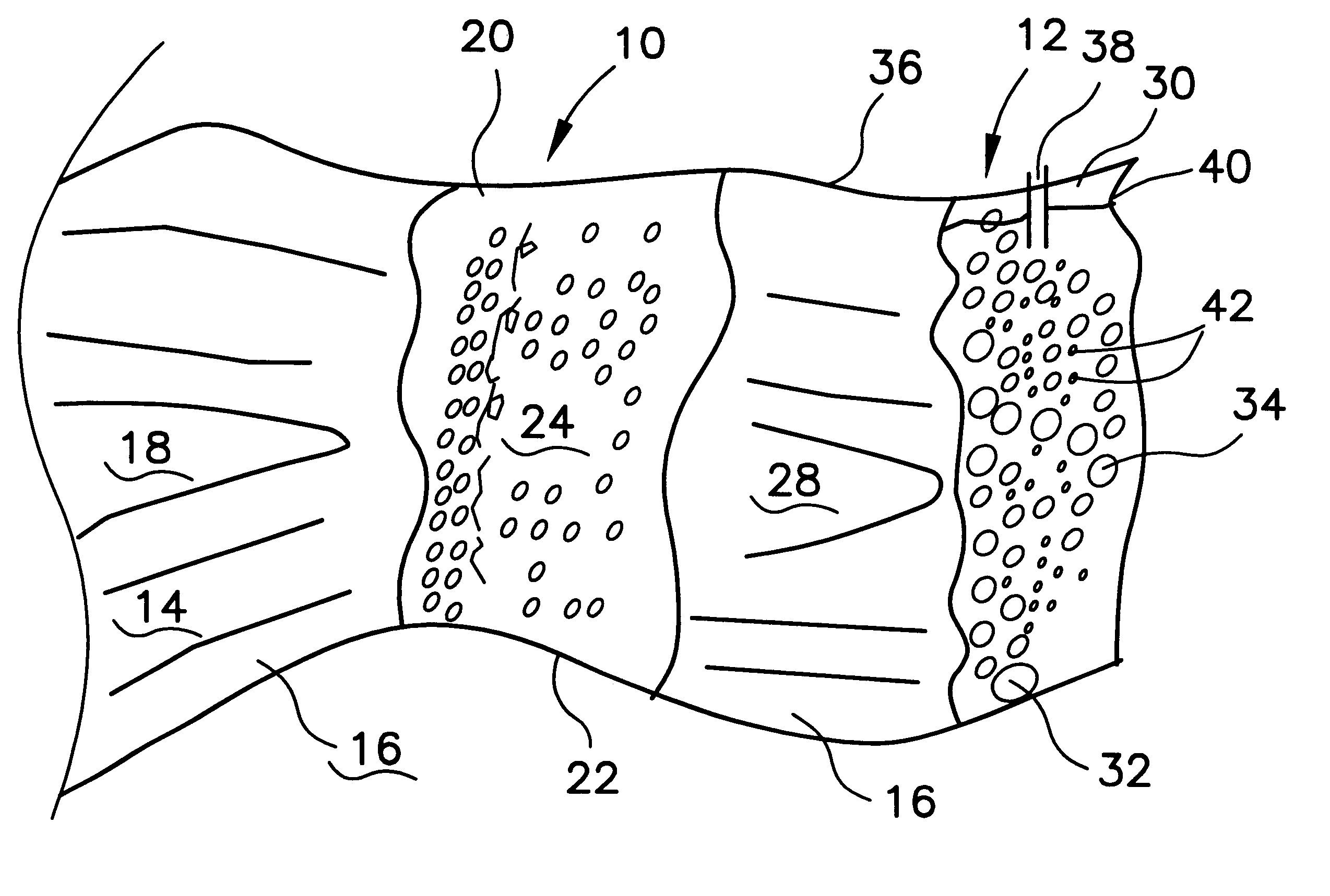
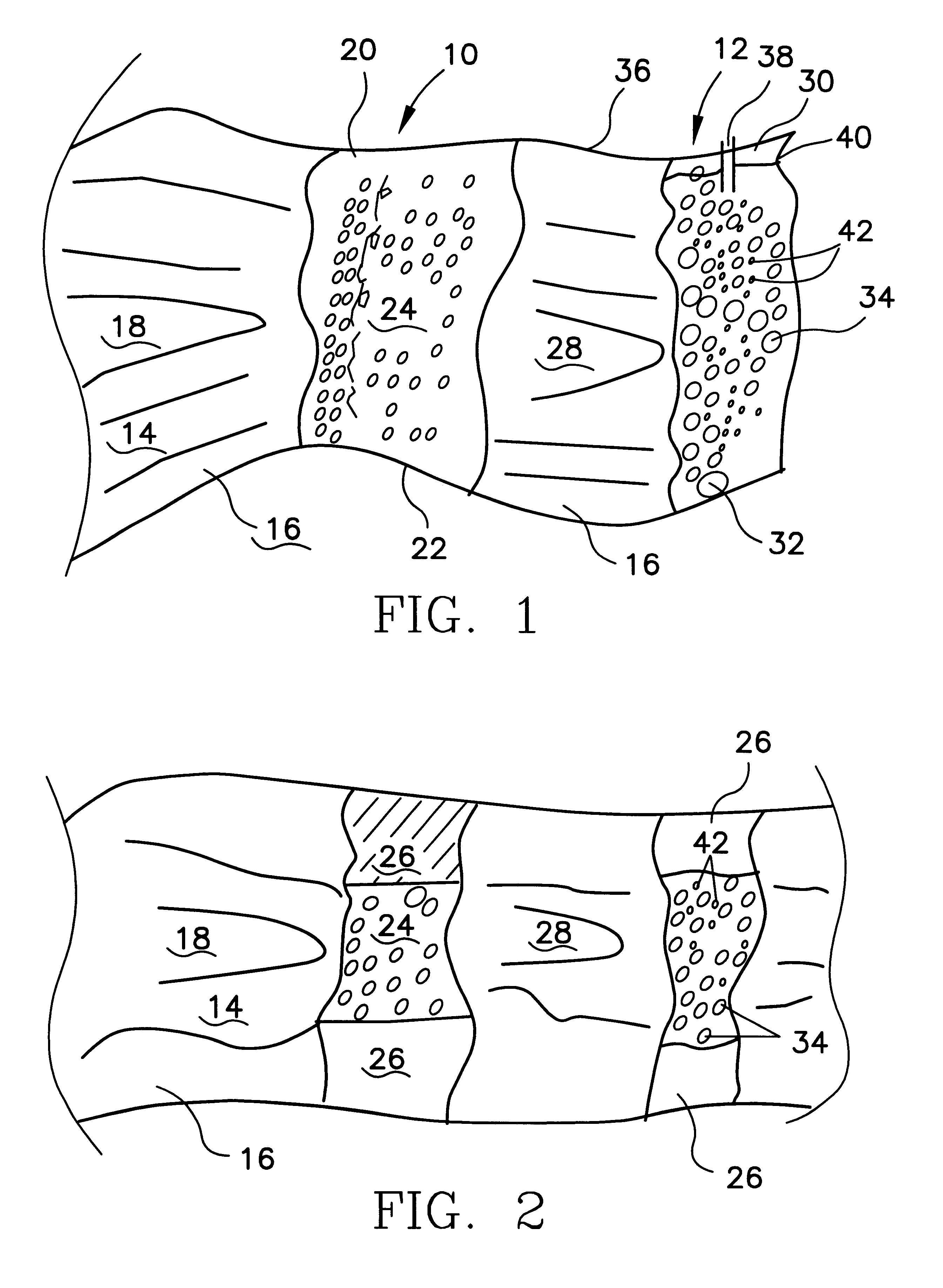
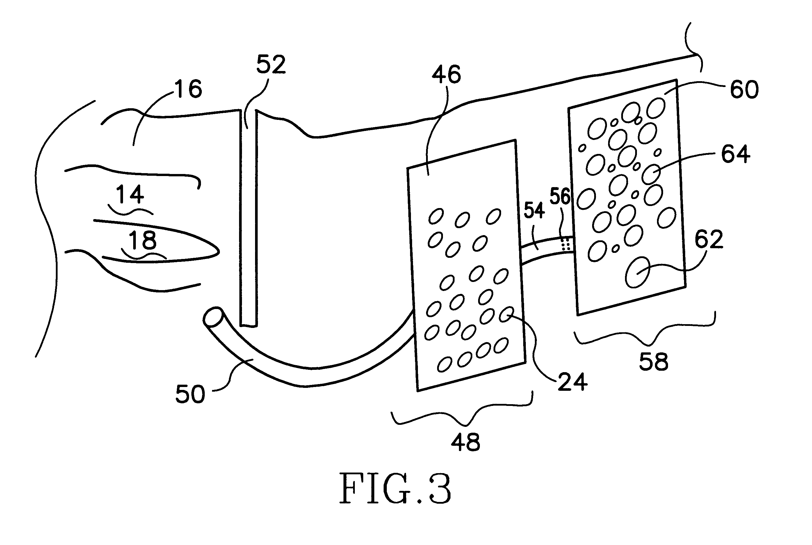
Referring to FIG. 1 a typical first in-situ groundwater treatment system is shown generally at 10. The improvement of this invention is shown generally at 12. Under normal condition groundwater 14 flows though an aquifer 16. A zone of contamination 18, within the aquifer 16, contains manmade or natural impurities that have entered the aquifer 16 and which contaminants are carried by the flow of groundwater 14. The typical first in-situ treatment system 10 includes a trench or repository 20 formed within the aquifer 16, generally perpendicular to the flow of groundwater 14 through the aquifer 16 and down to the underlying bedrock 22. The repository is filled with primary treatment media 24, such as active metals, activated carbon, limestone, or a biological agent. Typically, when the repository 20 is to be placed across the aquifer 16 for a significant distance, a portion of the repository may be filled with an impermeable material to form a barrier 26 across the aquifer 16, as sh...


PUM

PropertyMeasurementUnit
distanceaaaaaaaaaa
volume percentaaaaaaaaaa
permeabilityaaaaaaaaaa

Abstract

This invention is directed to a process for treating the flow of anaerobic groundwater through an aquifer with a primary treatment media, preferably iron, and then passing the treated groundwater through a second porous media though which an oxygenated gas is passed in order to oxygenate the dissolved primary treatment material and convert it into an insoluble material thereby removing the dissolved primary treatment material from the groundwater.

Description

1. Field of the InventionThis invention relates to the removal of iron and manganese from groundwater. More particularly, this invention relates to the removal of iron and manganese released from the treatment media of a primary in-situ groundwater treatment system.2. Description of Related ArtGroundwater in many localities has become contaminated by both natural and manmade impurities. Due to the considerable reliance on groundwater as a primary source of potable water, treatment of polluted groundwater to remove such contaminants has gained significant interest within the last decade. Many treatment systems for the removal of groundwater contaminants have been proposed, including pump-and-treat systems, well injection of treatment agents, and in-situ treatment. Due to the significant cost savings, in-situ treatment of groundwater has drawn considerable interest in recent years. In-situ treatment of groundwater is discussed in NEW APPROACH TO IN-SITU TREATMENT OF CONTAMINATED GROUN...

Claims


Application Information

Patent Timeline
Patent Type & Authority Patents(United States)
IPC IPC(8): B09C1/00
CPCB09C1/002
Inventor CARPENTER, CLAY E.MORRISON, STANLEY J.
Owner THE UNITED STATES AS REPRESENTED BY THE DEPARTMENT OF ENERGY
Learn More