
Tool coupling having serrated surfaces adapted to be pulled into meshing relationship

a technology of tool couplings and serrated surfaces, applied in the direction of chucks, turning machine accessories, rod connections, etc., can solve the problems of complicated and time-consuming tool exchange, affecting the quality of tooling,

Inactive Publication Date: 2001-06-12
SANDVIK INTELLECTUAL PROPERTY AB
View PDF10 Cites 44 Cited by
  • Summary
  • Abstract
  • Description
  • Claims
  • Application Information

AI Technical Summary

Benefits of technology

The present invention aims at removing the shortcomings mentioned above in connection with previously known tool couplings of the type in question and at providing an improved coupling. Thus, a primary object of the invention is to create a tool coupling by means of which the necessary tool exchanges are effected in a quick and simple way. A further object is to create a tool coupling that makes it possible to design one and the same holder in such a way that it may be used in a flexible way not only for cooperation with different types of adapters, but also for positioning adapters in several different positions. Still a further object of the invention is to create a tool coupling where there is no risk of losing said clamping means.

Problems solved by technology

However, a disadvantage in connection with the previously known tool coupling is that the exchange of the cutting head is complicated and time-consuming.
Thus, not less than three screws must initially be loosened and then again tightened to complete a tool exchange, which might take several minutes.
The tool exchanges become especially difficult in cases when the screws are hard to reach and / or have chips, dirt, grease deposits or the like in their key recesses.
Under such circumstances the operational shutdowns for tool exchanges may be very time-consuming and expensive.
Further, there is a risk of screws becoming lost since they must be loosened completely in order to allow dismounting of the cutting head.
Even if the number of screws for fastening the adapter to the holder in these cases is reduced to one and two, respectively, the operation to initially loosen a comparatively long screw and then again tighten said screw, after a tool exchange has been effected, results in the exchange taking a comparatively long time.
Also in this case the screws may become lost.

Method used


Image

  • Tool coupling having serrated surfaces adapted to be pulled into meshing relationship
  • Tool coupling having serrated surfaces adapted to be pulled into meshing relationship
  • Tool coupling having serrated surfaces adapted to be pulled into meshing relationship

Examples


Embodiment Construction

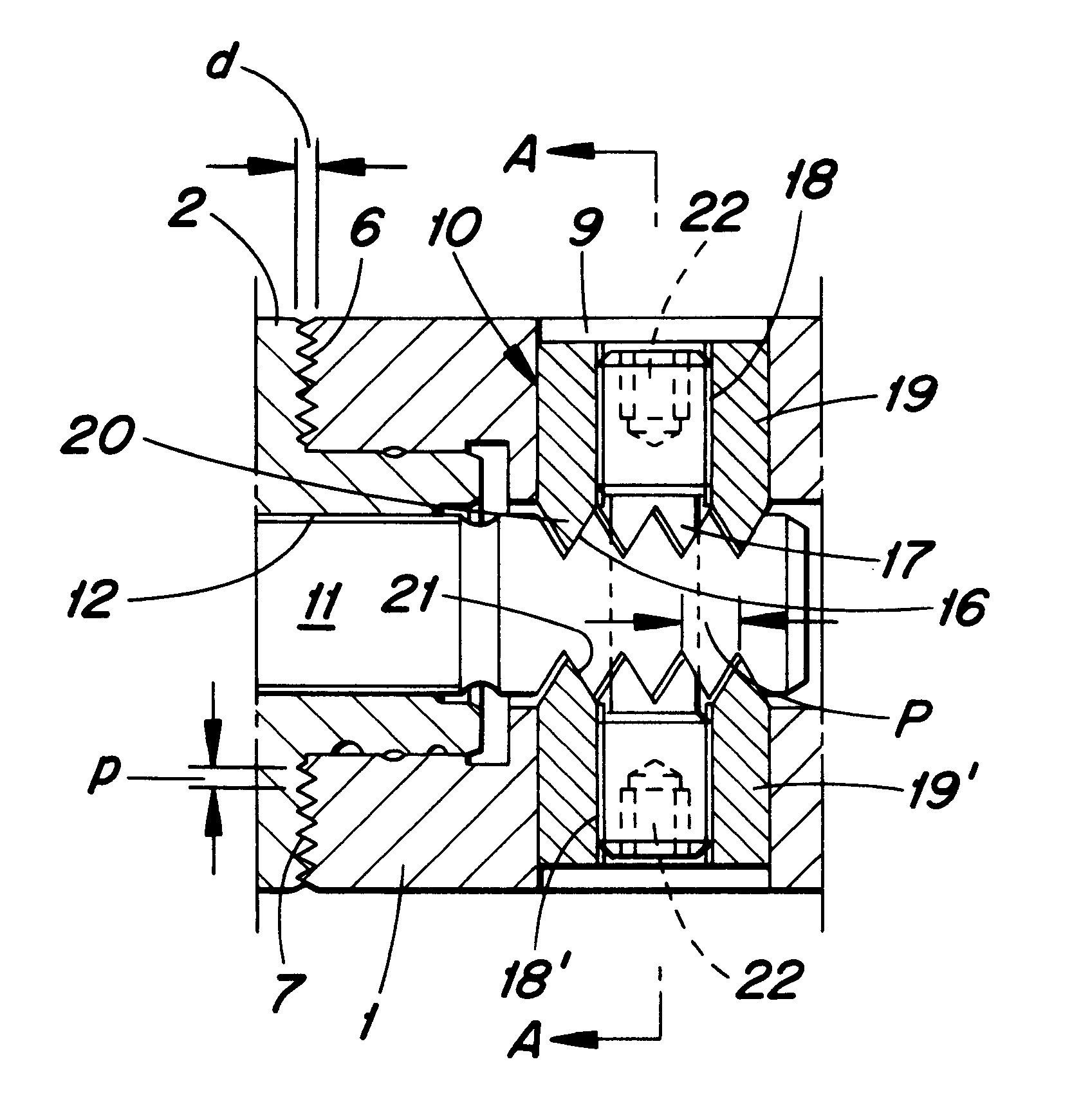
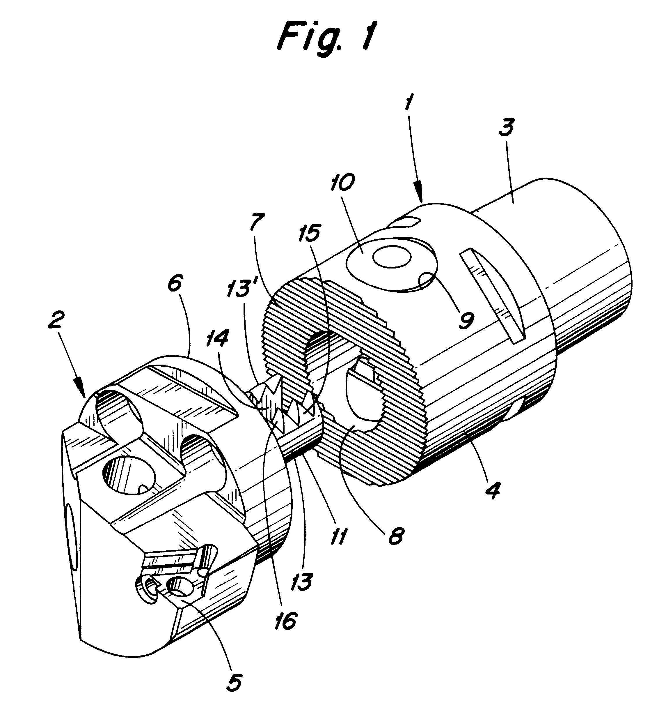
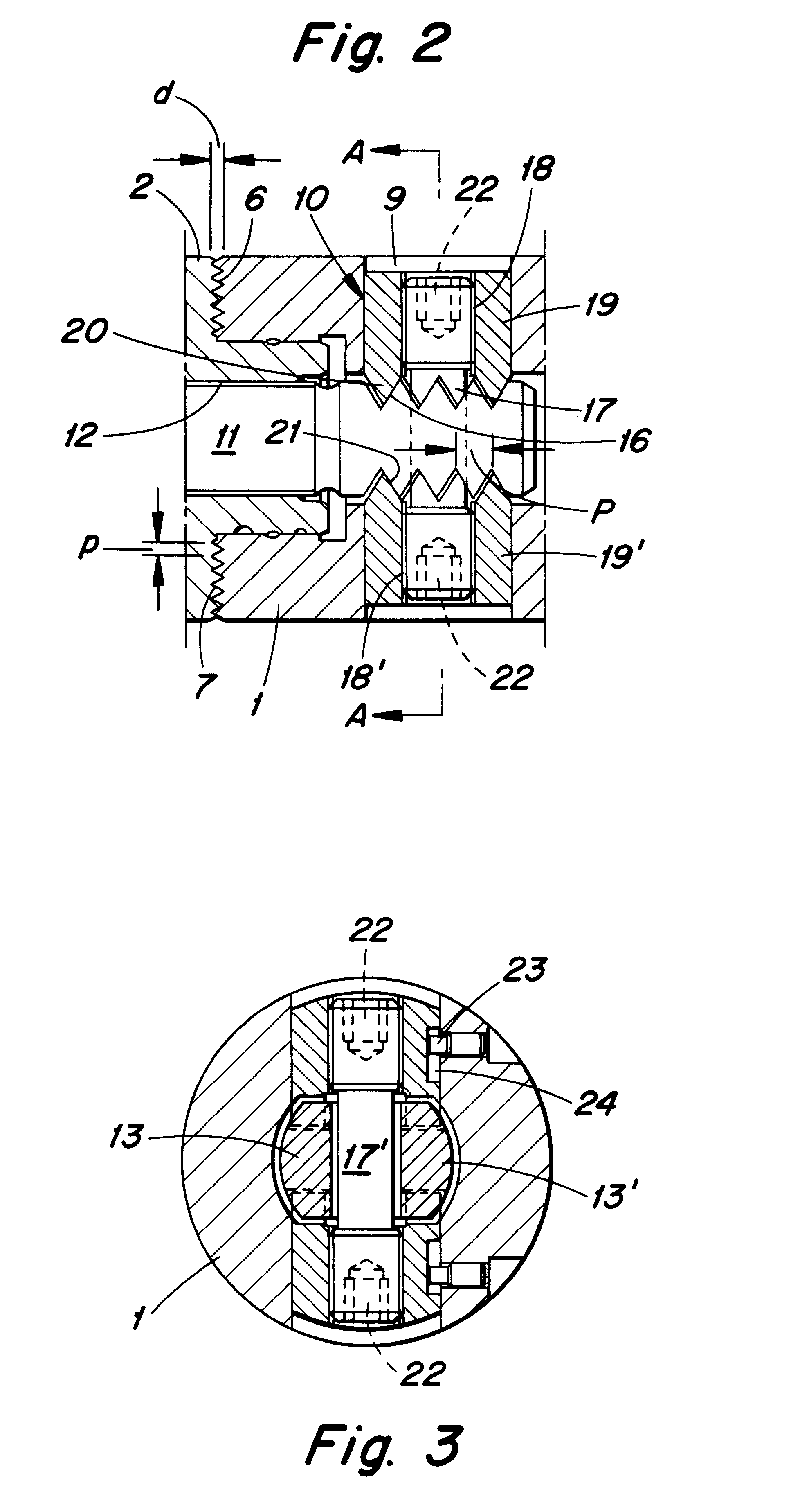
In FIGS. 1-3 reference numeral 1 designates a holder and reference numeral 2 designates an adapter. The holder 1, in practice called a basic holder, includes a rear portion 3 that is intended to be connected to a machine tool, for instance a multi-purpose lathe, and a forward portion 4, to which the adapter 2 is to be connected. The adapter in turn is constituted by a cutting head having at least one seat 5 for receiving a cutting insert or a machining element (not shown) for chip removing machining. At a rear end surface of this cutting head (hidden in FIG. 1) a first serration 6 is provided (see also FIG. 2). A corresponding serration 7 is provided at a forward end surface of the essentially cylindrical holder 1. This forward end surface extends perpendicular to the central longitudinal axis of the holder.

As so far described, the disclosed tool coupling features are essentially known on one hand from commercially available couplings of the type COROMANT CAPTO.RTM. and on the other...


PUM

PropertyMeasurementUnit
Angleaaaaaaaaaa
Depthaaaaaaaaaa

Abstract

A tool coupling includes first and second bodies held together by a clamping mechanism. The first body includes a first surface having a first serration formed therein, a first hole extending through the first surface, and a side surface having a second hole extending therethrough and intersecting the first hole. The second body includes a second surface facing the first surface and including a second serration configured to mesh with the first serration. A drawbar projects from the second surface and extends into the first hole. The drawbar includes a plurality of wedge surfaces. The clamping mechanism includes a screw disposed in the second hole and nuts threadedly mounted thereon for movement toward and away from the drawbar. Each nut includes a plurality of wedge surfaces arranged to engage the wedge surfaces of the drawbar to pull the second body toward the first body in a manner bringing the first and second serrations into meshing engagement with one another.

Description

This invention relates to a tool coupling of the kind that comprises a holder and an adapter for at least one cutting machining element, said adapter including a first serration intended to co-operate with a second serration of the holder, more precisely by bringing the serrations into engagement by means of a clamping means while providing a torque resistant connection between the adapter and the holder.PRIOR ARTWithin the field of chip removing machining there are tool couplings of the general kind defined above in several different applications, however, usually in turning tools of different type. Thus under the trade name COROMANT CAPTO.RTM. (Manufacturer: Sandvik AB, Sweden) boring bars are marketed, said boring bars utilizing such couplings. The holder of the coupling constitutes, for instance, a bar for receiving an adapter in the form of a cutting head, the coupling being mountable in a multipurpose lathe. The cutting head has one or more machining elements in the shape of e...

Claims


Application Information

Patent Timeline
IPC IPC(8): B23B29/00B23B29/04B23B31/10B23B31/107B23Q3/12B23B29/12
CPCB23B29/046B23B31/1076B23B2260/132Y10T409/30952Y10T403/7067Y10T403/32368Y10T408/953Y10T279/17675
Inventor HANSSON, PER
Owner SANDVIK INTELLECTUAL PROPERTY AB
Learn More