
Sea electrode for a high voltage direct current transmission system

a high-voltage direct current and electrode technology, which is applied in the direction of insulated conductors, connection contact material, cables, etc., can solve the problems of high local electric field strength in sea water, low average current density, and difficult to provide such electrodes with mechanical protection

Inactive Publication Date: 2001-06-05
ABB (SCHWEIZ) AG
View PDF9 Cites 7 Cited by
  • Summary
  • Abstract
  • Description
  • Claims
  • Application Information

AI Technical Summary

Problems solved by technology

However, ground electrodes are required also in HVDC transmission systems intended for bipolar transmission to transfer unbalance currents and, under operation in monopolar mode, the whole DC current transmitted by the HVDC system.
Ground electrodes for HVDC transmission systems, transferring comparatively high currents, operate, however, with a low average current density, and therefore often cover large areas at the sea bottom.
However, an inhomogeneous current distribution with high local current densities on the surface of the electrode body, in particular at peripheral parts of the electrode and at feeding points of the sub-electrode elements, results in high local electric field strength in the sea water.
Usually, it is more difficult to provide such electrodes with mechanical protection than it is with the electrodes intended for anodic operation, as described above, and typically they will also exhibit high current densities and consequently, high electric field strengths in the sea water in the vicinity of the electrode.
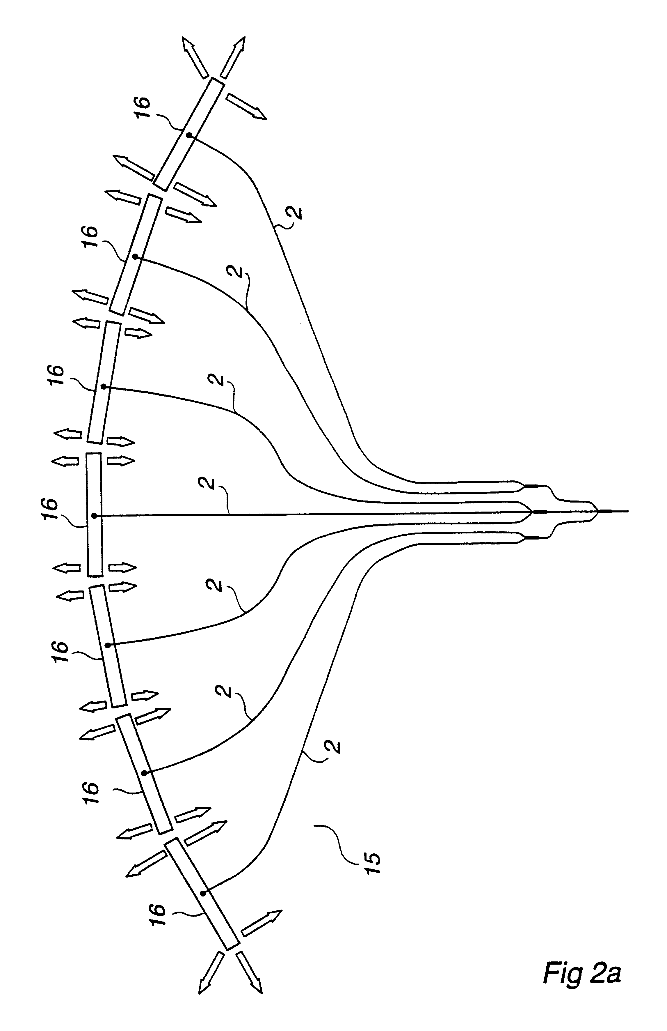
One disadvantage with the known sea electrodes is that they typically have a high local electric field strength, usually at the peripheral parts of their surface and at the locations where the feeder cables are connected.
As already mentioned, the electric field strength may have a harmful effect on fish and possibly also other aqueous organisms in the vicinity of the electrode.
Another disadvantage with the known sea electrodes is that they usually are designed to operate with a low average current density on the surface of the electrode body in order to keep the maximum electric field strength at a desired value, typically in the order of 1 A / m.sup.2.
One consequence is that the electrodes are poorly utilized and another is that they often occupy large areas, and thus may influence local conditions in the sea, such as for instance water streams.
Still another disadvantage with the known sea electrodes is that the ballast executed as a layer of gravel can under certain circumstances, such as strong waves or anchoring of large ships, be destroyed, leaving the electrode unprotected or even damaged and difficult to repair.
This is the reason why such electrode body materials as magnetite, graphite and silicon iron, which are mechanically brittle or fragile, have a very restricted use for sea electrodes.

Method used


Image

  • Sea electrode for a high voltage direct current transmission system
  • Sea electrode for a high voltage direct current transmission system
  • Sea electrode for a high voltage direct current transmission system

Examples


Embodiment Construction

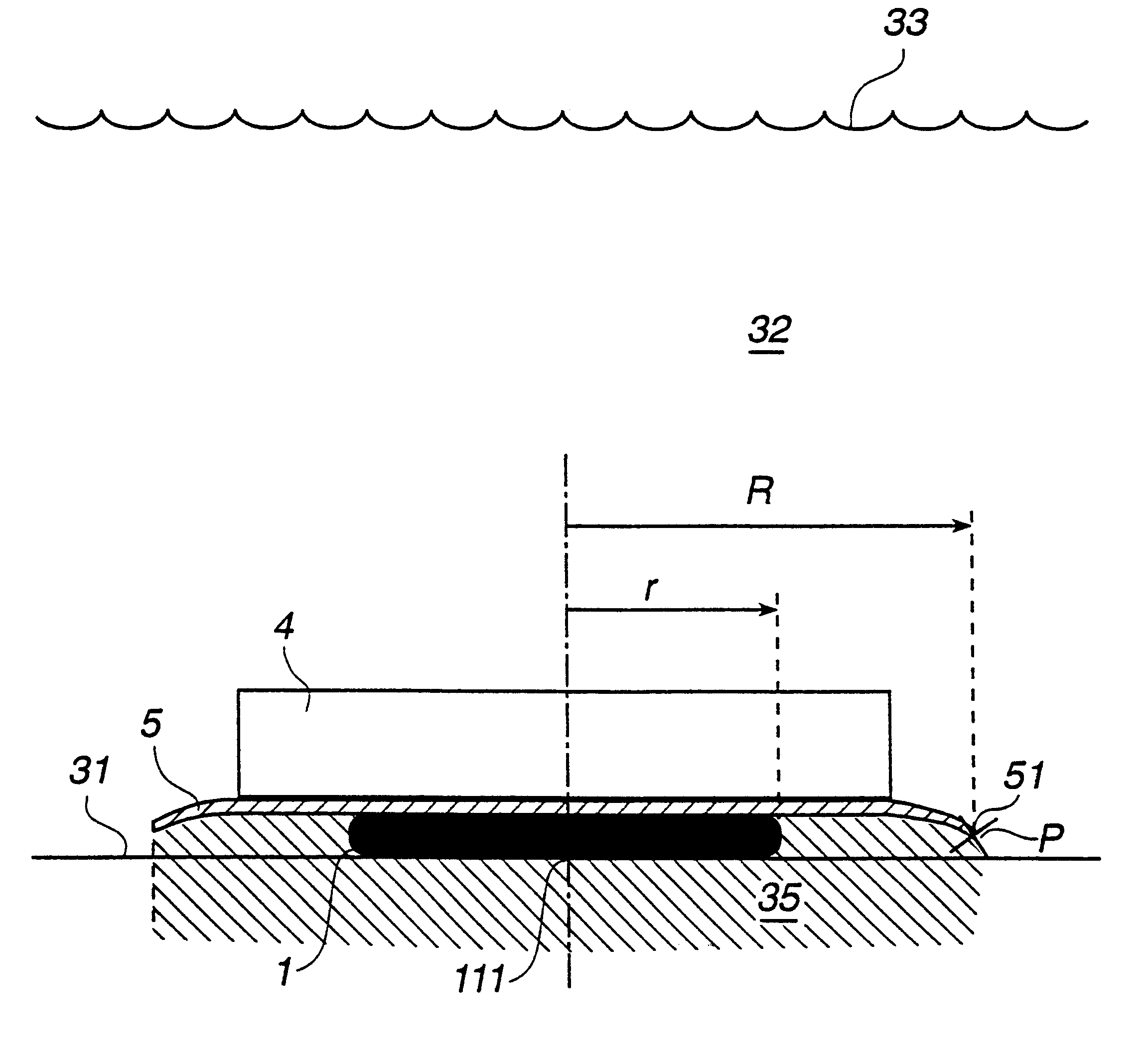
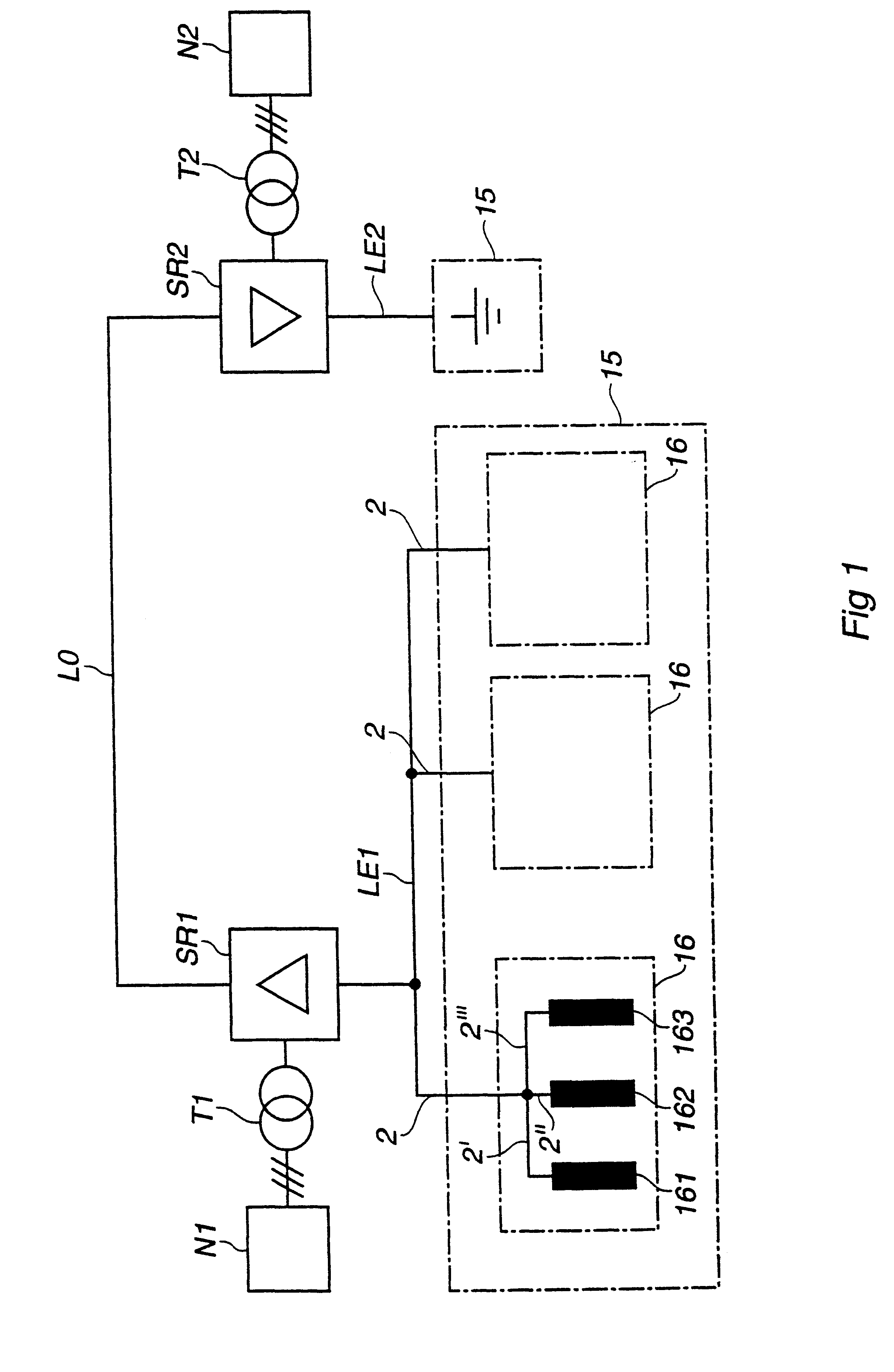
FIG. 5A shows schematically a cross section in a side view of a prior art sea electrode with a mesh-type sub-electrode element 161 as active part, and a ballast 4 in the form of a gravel layer. The sub-electrode element is located at the sea bottom 31, has the length 2L in the plane of the drawing and is fed at its midpoint, as illustrated in FIG. 3C, from a feeder cable 2.

The specific conductivity of the sea water and of the sea bottom are usually several orders of magnitude below the specific conductivity of the material of the electrode body.

It should be noted that the equivalent specific conductivity of a gravel layer above the electrode, although lower than the conductivity of the sea water, is high enough to allow for currents to penetrate the layer and reach the sea water. This is the case also for a massive ballast made of concrete, which becomes electrically conducting after being immersed into sea water for some time. Thus, in a configuration according to FIG. 5A, the elec...


PUM


Abstract

A sea electrode (15) for grounding of a high voltage direct current transmission system comprises an electrically conducting electrode body (1) for connection to the transmission system and at least one ballast (4) located above the electrode. The electrode further comprises a layer (5) of an electrically non-conducting material, located above the electrode body and extending over it, so as to influence the maximum electrical field strength not to exceed a desired level at a point (P) at the edge of the non-conducting layer and thereby also in the sea water outside a zone (35) located below the non-conducting layer and in a vertical direction limited by the edge of the non-conducting layer.

Description

The invention relates to a sea electrode for grounding of a high voltage direct current (HVDC) transmission system.BACKGROUND ART, DISCUSSION OF THE PROBLEMGround electrodes means in this context devices used to connect an electrode line of a power network comprising an HVDC transmission system, via one or more feeder cables, to a conducting medium such a soil or sea water.HVDC transmission systems usually have DC voltages above 5 kV and a transmitted power above 10 MW.As compared with alternating current (AC) transmission systems, HVDC transmission systems require only two conductors. At least one of those conductors is executed as an overhead line or a high voltage cable. For bipolar transmission another conductor of the same kind is used under normal operating conditions, but in monopolar transmission, the ground, that is soil and / or sea water, is used as return conductor for the transmitted DC-current. However, ground electrodes are required also in HVDC transmission systems int...

Claims


Application Information

Patent Timeline
IPC IPC(8): H02G9/00H02G9/02H01R3/00H01R3/08H01R4/66
CPCH01R3/08H02G9/02H01R4/66
Inventor IOSSEL, YURIKAZAROV, GRIGORYKOSKI, VEIJOPOLIAKOV, ALEXEYGEBHARDT, HEIKO
Owner ABB (SCHWEIZ) AG
Learn More